
Instruction Manual


2-10
SP120 AC Drive Installation and Operation
English
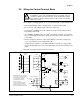
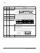
CM2 Reference potential for
outputs 11 and 12
Transistor output, max. 27 Vdc, 50 mA
The outputs can be programmed as either NO (active high) or
NC (active open) contacts using parameter C31 [
DIGITAL
OUTPUT 11LOGIC] and C32 [DIGITAL OUTPUT 12 LOGIC].
The following 6 settings may be programmed using parameter
C21 [
DIGITAL OUTPUT 11] and C22 [DIGITAL OUTPUT 12]:
00{RUN} = Motor Running (Signal if output frequency > 0.5 Hz)
01{FA1} = At frequency (Signal when the set frequency is
reached and that frequency is > 0.5Hz)
02{FA2} = Above frequency (Signal if output frequencies >
the
frequencies set under parameter C42 [
ABOVE
FREQUENCY ACCEL SETTING] or C43 [ABOVE
FREQUENCY DECEL SETTING] and > 0.5 Hz).
03{OL} = Motor overload (Signal if the motor current exceeds
the value set under C41 [
OVERLOAD ALARM SETTING]
04{OD} = PID-deviation (Signal if the deviation between the set
value and the actual value returned is greater than the
value set under C44 [
PID DEVIATION SETTING]). Only
available if the PID control A71 [
PID ENABLE] is active.
05{AL} = Fault (Signal if a fault is indicated)
12 Programmable Digital Output
11 Programmable Digital Output
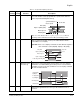
AL0 Fault Relay
Parameter C33 [
FAULT RELAY AL1 LOGIC] can be used to invert
the operation.
The fault relay is set with a time delay of approximately 2 sec
after the power is switched on.
AL1
AL2
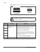
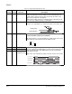
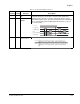
Table 2.4 – Control Terminal and Fault Relay Terminal Descriptions
Control
Terminal Function Description
AL0
AL1
AL2
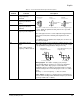
∼
230VAC
250 VAC, 2.5 A resistive
0.2A inductive
30 VDC, 3.0A resistive
0.7A inductive
min. 100 VAC, 10mA
5 VDC 100 mA
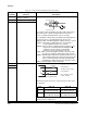
Faulted / De-energized State
C33 C33 = 01 C33 = 00
AL0 - AL1 Open when Faulted
Open when Power Off
Closed when Faulted
Open when Power Off
AL0 - AL2 Closed when Faulted
Closed when Power Off
Open when Faulted
Closed when Power Off