
Instruction Manual


Installing and Wiring the Drive
2-9
English
H 10 V Reference Voltage for
Analog Frequency
Command
Input OI for 4-20 mA is activated when one of the digital inputs
is set to 16{AT} via parameters C01 [
DIGITAL INPUT 1] to C05
[
DIGITAL INPUT 5].
The analog input reference can be adjusted using parameters
A11 [
ANALOG FREQUENCY MINIMUM] to A16 [ANALOG FILTER
SELECT].
If no digital input is programmed as 16{AT}, the set values are
the sum of O and OI.
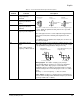
O Voltage Analog Input
Frequency Command
(0-10 V)
OI Current Analog Input
Frequency Command
(4-20 mA)
L 0 V Reference Potential for
Frequency Comand Inputs
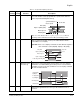
FM Programmable Analog
Output
Analog or Pulse Output
Frequency or Motor Current
This output can be used to monitor the output frequency of the
drive (either Analog or Pulse) or the motor current. This output
is programmable using parameter C23 [
OUTPUT FM].
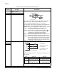
Analog Signal: The relation t/T (duty cycle) changes
proportionally with the frequency or current. The maximum
voltage of 10V (100% duty cycle) is reached when the
maximum frequency or 200% of the rated current is reached.
Parameter b81 [
OUTPUT FM FACTOR] may be used as a scaling
factor.
Accuracy: +/- 5% for frequency , +/- 20% for current
Pulse Signal: Frequency = output frequency x b86 [
PROCESS
DISPLAY SCALE FACTOR], but the maximum frequency is 3.6 kHz
(ex. Freq = 60Hz x 60 = 3.6kHz).
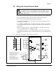
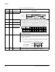
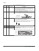
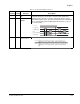
Table 2.4 – Control Terminal and Fault Relay Terminal Descriptions
Control
Terminal Function Description
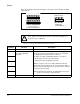
Potentiometer
1 to 2 kOhm
Input impedance
10 kOhm
Input impedance
250 Ohm
H
O
OI
L
H
O
OI
L
H
O
OI
L
+
-
4-19.6 mA0-9.6 V
+
PE PE
PE
nominal 0-10 V nominal 0-20 mA
Analog Signal
Frequency or Current
Pulse Signal (50% duty cycle)
Frequency only
T = 4 ms (constant) T = (Variable)