
Instruction Manual


2-2
SP120 AC Drive Installation and Operation
English
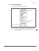
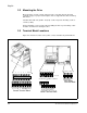
2.2 Mounting the Drive
Mount the drive on a flat, vertical, and level surface. The drive must be mounted
vertically (top up) for proper heat dissipation. Refer to Appendix A for drive mounting
dimensions.
Install the drive with four (4) M4 x .07 (8-32) screws. Torque the mounting screws to
1.2 Nm (11 lb/in).
Ensure that debris cover is in place when installing the drive to prevent filings, cable
insulation and dust from entering the drive.
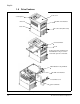
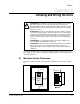
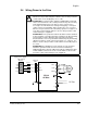
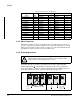
2.3 Terminal Block Locations
Figure 2.2 shows the locations of the power, control, and fault relay terminal blocks.
Figure 2.2 – Terminal Block Locations
L 5 4 3 2 1 P24
Control terminal block
HO0I L
FM CM
21211
+1
+
* *
L1 N/L3
Power terminal block, AA01 - AA03 ratings only
U/T1 V/T2W/T3
L2
*
(/)
+1
-
L1 N/L3
U/T1 V/T2W/T3
*
Not Used
-
+
Power terminal block, all ratings except AA01 -AA03
L2
AL0
Fault relay
terminal block
AL1 AL2
Fault Relay
Terminal Block
All other model numbers
S12-20015LU only - L1, L2, L3
Control Terminal Block
S12-201P4LU / 202P6LU / 203P0LU
*
*
*
––
* Not used
Power Terminal Block
–