
User Manual


Setting Up the Demo Unit
2-1
C
HAPTER
2
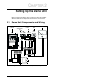
Setting Up the Demo Unit
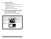
Before running the demo, take a moment to become familiar
with the demo unit components and how the unit is wired.
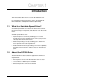
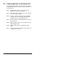
2.1 Demo Unit Components and Wiring
Figure 2.1 – SP120 AC Drive Demo Components and Wiring
RUN
RUN
A
A
MIN
MIN
MAX
MAX
PRG
PRG
Hz
Hz
FWD/REV STOP/RUN LAMP
SPD POT
METER
FUSE
BLUE
BLUE
T1
U
RED
T3
W
BLACK
V
T2
SEC.
230V
BLUE
NL1
YELLOW
ORANGE
12
P24
11
WHITE
LFMCM2
GRAY
VIOLET
2
RED
1
BROWN
3
HOO1
BLUE
GREEN
45L
BLACK
JUMPER
MOTOR
TRANSFORMER
GND
AC INPUT
GND
C01
C02
CONF OUT
SPEED
SP120
DRIVE
TOGGLE
SWITCHES
INDICATOR
LAMP
SPEED
POT
METER