Using the SP120 AC Drive Demo Unit M/N D1SP1201 Instruction Manual D2-3471
The information in this manual is subject to change without notice. Throughout this manual, the following notes are used to alert you to safety considerations: ! ATTENTION: Identifies information about practices or circumstances that can lead to personal injury or death, property damage, or economic loss. Important: Identifies information that is critical for successful application and understanding of the product.
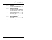
CONTENTS Contents Chapter 1 Introduction 1.1 What is a Variable-Speed Drive?....... 1-1 1.2 About the SP120 Drive ...................... 1-1 Chapter 2 Setting up the Demo Unit 2.1 Demo Unit Components and Wiring .. 2-1 2.2 Connecting Power to the Demo Unit . 2-2 Chapter 3 Programming Basics 3.1 Parameter Menu Structure ................3-1 3.2 Parameter Types ............................... 3-2 3.3 How to Display and Adjust Parameter Values Using the Keypad. 3-2 Chapter 4 Running the Demo Unit 4.
II Using the SP120 AC Drive Demo Unit
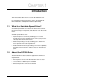
CHAPTER 1 Introduction This manual describes how to use the SP120 demo unit. For complete product information, refer to the SP120 AC Drive Installation and Operation Manual (D2-3456). 1.1 What Is a Variable-Speed Drive? A variable-speed drive is an electronic device that controls the speed, torque, horsepower, and direction of an AC or DC motor.
The SP120 drive comes standard with four control selections to meet specific application requirements: • Speed potentiometer • Single-channel analog input • Preset speeds (up to 15) • PID 1-2 Using the SP120 AC Drive Demo Unit
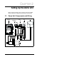
CHAPTER 2 Setting Up the Demo Unit Before running the demo, take a moment to become familiar with the demo unit components and how the unit is wired. 2.
2.2 Connecting Power to the Demo Unit The SP120 AC drive demo unit is powered by a grounded 115 VAC input. Follow these steps to connect the power cord to the demo unit. Step 1. Stand the demo unit on a flat surface with the handle and cover latches facing you. Step 2. Open both latches and lift the cover. Then slide the cover to the right to remove. Step 3. The power cord is stored in the cover of the demo unit. Press down on the spring-loaded fasteners inside the cover to access the power cord. Step 4.
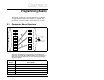
CHAPTER 3 Programming Basics To program the drive for a specific application, you display the appropriate parameter and adjust it as required. The parameters are used to define characteristics of the drive. 3.1 Parameter Menu Structure d01 A01 d16 A98 PROG F01 b01 F04 PROG Parameter Entry PROG b92 Saving entered Parameters d01 A .. PROG b .. C01 C91 C .. Figure 3.
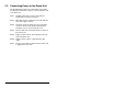
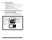
3.2 Parameter Types There are three types of parameters: • Tunable parameters can be adjusted or changed while the drive is running or stopped. • Configurable parameters can be adjusted or changed only while the drive is stopped. • Read-only parameters cannot be adjusted. 3.3 How To Display and Adjust Parameter Values Using the Keypad The keypad is located on the front panel of the drive. You must open the cover to access the programming keys. Run LED is on when drive is responding to start command.
Table 3.1 – Key Descriptions Key PROG Description • Toggles between parameter number and parameter value. • Selects the parameter group or individual parameter. • Scrolls through parameters or parameter groups. • Increases or decreases parameter values. Enters the displayed value into memory. When the Start key is active, starts the motor in the direction of rotation defined in F04 [START KEY DIRECTION]. • Stops the motor. • Clears drive faults.
3-4 Using the SP120 AC Drive Demo Unit
CHAPTER 4 Running the Demo Unit The demo consists of three step-by-step labs to acquaint you with the basic operation of the drive. Purpose of the labs: 4.1 Lab A Learn the steps required to reset the drive to factory defaults. This lab sets the drive up for the next two labs. Run Lab A first. Lab B Learn how to set up and run the drive in local (keypad) operation. Lab C Learn how to set up and run the drive in remote (switches and speed pot) operation.
Step 9. Press and hold PROGram, ▲, ▼, and for 3 seconds. Step 10. Release only. Hold the other keys down until the display starts to blink, then release the remaining keys. d01 will be displayed when the defaults have been successfully restored. Lab B: Set up the drive for local (keypad) operation using the following procedure: Tools required: None Step 1. Use the PROGram and ▲ ▼ keys to select the F parameter group. Step 2. Set F02 [ACCEL TIME] to 3.0 sec. Step 3. Set F03 [DECEL TIME] to 3.0 sec. Step 4.
Lab C: Set up the drive for remote operation (based on 2wire start stop). Tools required: None Step 1. Set parameter A01 [FREQUENCY COMMAND SELECT] to equal 01. This changes the source of the drive’s speed reference to an analog reference. Step 2. Start the drive by pressing . Notice that the RUN are on. LED and the LED above a. Turn the speed pot located on the drive. Notice there is no effect. Start/Stop is still from the drive. b. Turn the remote speed pot. Notice that now you can vary the speed.
Running the Demo Unit 4-4
CHAPTER 5 Troubleshooting the Demo Unit Use table 5.1 to troubleshoot any problems you may have with the demo unit. For technical assistance, call 1-800-726-8112. Table 5.1 – Troubleshooting Table Problem Display or LEDs are not on. Corrective Action • Check power source. • Check power cord connection. • Check on/off switch. • Check fuse. Demo unit does not react as described in labs. • Verify that parameter defaults were restored. Cannot change parameter value.
5-2 Using the SP120 AC Drive Demo Unit
U.S. Drives Technical Support Tel: (1) 262.512.8176, Fax: (1) 262.512.2222, Email: support@drives.ra.rockwell.com, Online: www.ab.com/support/abdrives Publication D2-3471 - September 2000 Copyright © 2000 Rockwell Automation, Inc. All Rights Reserved. Printed in USA.