Using the SP200 AC Drive Demo Unit M/N D1SP2001 Instruction Manual D2-3474
The information in this manual is subject to change without notice. Throughout this manual, the following notes are used to alert you to safety considerations: ! ATTENTION: Identifies information about practices or circumstances that can lead to personal injury or death, property damage, or economic loss.T Trad Important: Identifies information that is critical for successful application and understanding of the product.
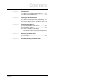
CONTENTS Contents Chapter 1 Introduction 1.1 What Is a Variable-Speed Drive? ...... 1-1 1.2 About the SP200 Drive ...................... 1-1 Chapter 2 Setting Up the Demo Unit 2.1 Demo Unit Components and Wiring .. 2-1 2.2 Connecting Power to the Demo Unit . 2-2 Chapter 3 Programming Basics 3.1 Parameter Menu Structure ................3-1 3.2 Parameter Types ............................... 3-1 3.3 How To Display and Adjust Parameter Values Using the Keypad. 3-2 Chapter 4 Running the Demo Unit 4.
II Using the SP200 AC Drive Demo Unit
CHAPTER 1 Introduction This manual describes how to use the SP200 demo unit. For complete product information, refer to Installing and Operating the SP200 AC Drive (D2-3408). 1.1 What Is a Variable-Speed Drive? A variable-speed drive is an electronic device that controls the speed, torque, horsepower, and direction of an AC or DC motor.
• Three-phase ratings available in both 230 V and 460 V. • Operator control options include local keypad or remote keypad. A CopyCat keypad is available for applications where quick editing and transfer of settings to multiple drives is desired. The SP200 drive comes in three different control models to match specific needs: • Model A: Single Channel Analog - for control from one analog signal or a speed pot.
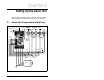
CHAPTER 2 Setting Up the Demo Unit Before running the demo, take a moment to become familiar with the demo unit components and how the unit is wired. 2.1 Demo Unit Components and Wiring L1 115 VAC L2 SP200 DRIVE TOGGLE SWITCHES STOP RUN GND SPEED POT INDICATOR LAMP CONF IN 0 1 CONF OUT ANALOG CHAN #1 ANALOG CHAN #2 R Gray Brown Fuse Green Red Violet Blue White Yellow Black Orange Brown Motor GND Figure 2.
2.2 Connecting Power to the Demo Unit The SP200 AC drive demo unit is powered by a grounded 115 VAC input. Follow these steps to connect the power cord to the demo unit. Step 1. Stand the demo unit on a flat surface with the handle and cover latches facing you. Step 2. Open both latches and lift the cover. Then slide the cover to the right to remove. Step 3. The power cord is stored in the cover of the demo unit. Press down on the spring-loaded fasteners inside the cover to access the power cord. Step 4.
CHAPTER 3 Programming Basics To program the drive for a specific application, you display the appropriate parameter and adjust it as required. The parameters are used to define characteristics of the drive. 3.1 Parameter Menu Structure The SP200 drive has two kinds of parameters: program parameters (P-xx), which configure the drive operation, and display parameters (d-xx), which display information regarding the drive status. Table 3.
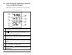
3.3 How To Display and Adjust Parameter Values Using the Keypad The keypad is located on the front panel of the drive demo unit. Table 3.2 – Keypad Description 1 9 2 8 3 7 4 6 5 1 2 The display shows either a parameter number or a parameter value. The parameter numbers are preceded by either a “P-” or a “d-”. The key toggles between display and program modes. The (5) turns on when the drive is in program mode and turns off when the drive is in display mode.
Table 3.2 – Keypad Description 7 8 9 The key issues stop and fault reset commands to the drive. The key issues start commands to the drive when P-10 = 1. In display mode, the key increments the local speed reference. In program mode, this key increments the parameter number or parameter value. The following table provides detailed steps for keypad operation. Table 3.3 – Keypad Operation Desired Action User Steps Start the unit Press to start the drive.
Table 3.3 – Keypad Operation Desired Action Increment the program parameter number User Steps 1. Press PR OG until the PROGRAM LED turns on to enter program mode. 2. Press Decrement the program parameter number until the desired number is displayed. 1. Press PR OG until the PROGRAM LED turns on to enter program mode. 2. Press Increment the current program parameter value until the desired number is displayed. 1. Press PR OG until the PROGRAM LED turns on to enter program mode. 2.
CHAPTER 4 Running the Demo Unit The demo consists of five step-by-step labs to acquaint you with the basic operation of the drive. Purpose of the labs: Lab 1 This lab has two parts: a. Learn the steps required to reset the drive to factory defaults. b. Learn how to set up a basic configuration that uses external I/O. This lab sets the drive up for the next four labs. Run Lab 1 first. 4.1 Lab 2 Learn how to use the display parameters to view drive status.
Step 3. Press or displayed. until P-60 [RESET TO DEFAULTS] is Step 4. Press to display the value of P-60 (0 should be displayed). Step 5. Press to change the value to 1(Reset All Values to Factory Defaults). Step 6. Press to accept the value. The drive’s factory defaults have been restored. Lab 1b: Setting up a basic drive configuration that uses external I/O control. Step 1. Press until the PROGRAM LED turns on to enter program mode. PR OG Step 2. Press or displayed. Step 3.
Table 4.1 – Parameter Values for Basic Configuration No. Parameter Name Value P-00 MINIMUM SPEED 5 Hz P-01 MAXIMUM SPEED 60 Hz P-02 MOTOR OVERLOAD CURRENT 0.4 A P-03 REVERSE DISABLE 0 P-05 CURRENT LIMIT 150% P-10 START CONTROL 2 (2-Wire Start) P-20 MAIN SPEED REFERENCE P-30 ACCELERATION TIME 1 P-31 DECELERATION TIME 1 P-34 STOP CONTROL 0 (Ramp-to-Rest) P-50 BASE VOLTAGE 100 V P-51 BASE SPEED 60 Hz 0 (Analog Input 1) 3.0 sec 3.
Lab 2: Using the display parameters to view drive status. Tools required: None Step 1. Press until the PROGRAM LED turns off to enter display mode. PR OG Step 2. Press once. The letter "d" will be displayed along with a two-digit number. Step 3. Continue to depress (multiple times) to cycle through all the display parameters. Note: When you stop or pause at a display parameter for more than 2 seconds, the value of that parameter is displayed. Step 4.
A configured output is an output that can be programmed to indicate various conditions. On the demo unit, the red CONF OUT indicator lamp is hardwired to the configurable output terminals on the drive’s terminal strip (terminals 11 and 12). In this lab, you will program the configured input as a function loss interlock and as a reversing switch. You will program the configured output to indicate various conditions. Before proceeding with this lab, do the following: Step 1.
Step 4. Turn the STOP/RUN switch to RUN. The motor should rotate to the commanded speed selected on the speed pot (ANALOG CHAN #1). Step 5. Turn the CONF IN switch from 1 to 0. Note the following things that occur: • The drive faults, and the motor coasts to a stop. • The drive displays the fault code FL (Function Loss). • The drive status LED changes from green (OK) to red (problem exists). • The RUN and PROGRAM LEDs turn off. Step 6.
If this fault occurs, turn the STOP/RUN switch to STOP and the CONF IN switch to 0. Then press to reset the fault. Lab 3c: Programming the configurable output. The red indicator lamp (CONF OUT) on the demo unit is hardwired to the configurable output on the terminal strip (terminals 11 and 12). Step 1. Set P-12 [CONFIGURABLE OUTPUT] to 0 (No Fault). This programs the output to turn on when the drive is not faulted. Step 2. Turn the STOP/RUN switch to RUN. (The motor should rotate). Step 3.
Step 11. Set P-13 [CONFIGURABLE OUTPUT LEVEL] to 30.0. This sets the level at which the output will turn on to 30.0 Hz. Step 12. Turn the speed pot (ANALOG CHAN #1) fully clockwise. The red indicator lamp should be on. Step 13. Press PR OG to enter display mode. Step 14. Press until d-01 [OUTPUT FREQUENCY] is displayed. Step 15. Slowly turn the speed pot counter-clockwise. Notice that the red indicator lamp turns off when the frequency drops below 30.0 Hz. Step 16. Set the sTOP/RUN switch to STOP.
Step 7. Press , if necessary, until d-01 [COMMAND is displayed. FREQUENCY] Step 8. Turn the STOP/RUN switch to STOP. Notice that the output frequency immediately drops to 0. Notice how long it takes the motor to stop. Lab 4b: Programming the drive for a ramp-to-rest stop. Step 1. Press PR OG to enter program mode. Step 2. Set P-34 to 0 (Ramp-to-Rest). Step 3. Press PR OG to enter display mode. Step 4. Press , if necessary, until the value of d-01 [COMMAND FREQUENCY] is displayed. Step 5.
Step 7. Turn the STOP/RUN switch to STOP. Notice that the output frequency and voltage dropped to 0 immediately. Step 8. Reset the following parameters: P-34 to 1 P-35 to 10 P-36 to 0.0 Lab 5: Setting up an avoidance frequency. Tools required: None Avoidance frequency parameters are used to prevent the drive from continuous operation within a range (band) of frequencies. Step 1. Set P-37 [AVOIDANCE FREQUENCY] to 30.0 Hz. This specifies the midpoint of the band. Step 2.
CHAPTER 5 Troubleshooting the Demo Unit Use table 5.1 to troubleshoot any problems you may have with the demo unit. For technical assistance, call 1-800-726-8112. Table 5.1 – Troubleshooting Table Problem Display or LEDs are not on. Corrective Action • Check power source. • Check power cord connection. • Check on/off switch. • Check fuse. Demo unit does not react as described in labs. • Verify that parameter defaults were restored. Cannot change parameter value.
5-2 Using the SP200 AC Drive Demo Unit
U.S. Drives Technical Support Tel: (1) 262.512.8176, Fax: (1) 262.512.2222, Email: support@drives.ra.rockwell.com, Online: www.ab.com/support/abdrives Publication D2-3474– November 2000 Copyright © 2000 Rockwell Automation, Inc. All Rights Reserved. Printed in USA.