
User guide

PowerFlex 700 Phase Monitor Relay Replacement
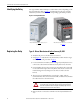
3. Locate terminals L1, L2 and L3 on the relay. Verify that the wires
connected to each terminal are labeled correctly, then remove the wires.
4. Locate the wires connected to terminals 25 and 28 of the relay and verify
that they are labeled correctly. Remove the wires from the relay.
5. Remove the end clamps from the DIN rail. Remove the relay and discard.
6. Mount the new relay to the DIN rail and install end clamps.
7. Connect wire numbers 25 and 28 to the corresponding terminals of the
new relay.
8. Connect the L1, L2 and L3 wires to the corresponding terminals of the
new relay.
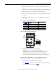
9. Verif y the following adjustments:
10. Apply power and check for proper operation.
If phasing is correct, the “R/T” LED will illuminate.
If phasing is not correct, the “F1” and “F2” LEDs will alternately
illuminate. Refer to the PowerFlex 700 Frame 7…10 Installation
Instructions, publication 20B-IN014 for troubleshooting information.
No.
(see Figure 2
) Adjustment Setting
➊ DIP Switches OFF
➋ Overvoltage Threshold Set to maximum (580V)
➌ Undervoltage Threshold Set to minimum (350V)
➍ Phase Unbalance Threshold Set to maximum (25%)
➎ Delay Set to minimum (0 s)
www.rockwellautomation.com
Amer
i
cas:
Rockwell
Automation, 1201 South
Second
Street,
Milwaukee,
WI 53204
-
2496
USA,
Tel:
(1)
414.382.2000, Fax: (1)
414.382.4444
Europe
/
Middle East
/
Africa:
Rockwell
Automati
on,
Pegasus
Park,
De Kleetlaan 12a,
1831 Diegem, Belgium,
Tel: (32) 2 663
0600, Fax: (32) 2 663
0640
Asia Pacific: Rockwell Automation, Level 14,
Core F,
Cyberport
3, 100
Cyberport Road,
Hong Kong,
Tel: (852) 2887 4788, Fax:
(852) 2508
1846
Power,
Control
and
Information Solutions
Headquarters
Publication 20B-IN027A-EN-P – March 2011 PN-111987
Copyright © 2011 Rockwell Automation, Inc. All rights reserved. Printed in USA.
U.S. Allen-Bradley Drives Technical Support - Tel: (1) 262.512.8176, Fax: (1) 262.512.2222, E-mail: support@drives.ra.rockwell.com,
Online: www.ab.com/support/abdrives
*PN-111987*
PN-111987