
Manual

Installation Guidelines
3-7
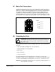
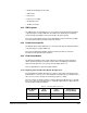
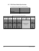
3.7 Meter Port Connections
Terminal block TB6 at the bottom of the control compartment contains four analog
output ports, as shown in figure 3.5. Each port can be connected to a separate analog
device (e.g., a meter or other data-logging device). The meter port output circuit is
described in the PMI Rack and Modules instruction manual (S-3008). Meter port
configuration is described in the Drive Configuration and Programming instruction
manual (S-3006). Please refer to these two manuals for further information on using
the meter ports. If not configured, the ports default to “not used” and output zero volts.
3.8 Grounding the Drive
To properly ground the drive, all of the following components of the system must be
grounded:
•
safety ground (PE) to building steel or floor ground loop
•
signal ground (TE) to zero potential bus
•
power feeder
•
motor connections
•
resolver connections
The TE and PE busbars run through the bottom of the drive’s enclosure. The
grounding conductors must be supplied by the user and must be adequately sized in
accordance with NEC/CEC and all applicable local, national, or international codes.
Important:
The TE and PE conductors must be separated by a minimum distance of
20 feet within the user facility.
Figure 3.5 – Meter Port Connections (TB6)
2468
1357
1357
2468
Terminal
1
2
3
4
5
6
7
8
+
COM
+
COM
+
COM
+
COM
Port 1
Port 2
Port 3
Port 4
TB6
}
}
}
}
!
ATTENTION:
Ungrounded equipment presents a shock hazard. Connect
the drive’s ground terminals to earth ground using properly-sized ground
wires. Failure to observe this precaution could result in severe bodily
injury or loss of life.