
Manual
3-6
SD3100 Power Modules
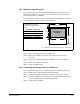
3.6 Installing Feedback Devices
All feedback devices interface to the SD3100 Power Module through the PMI
Regulator. Terminal blocks TB4 and TB5 at the bottom of the control compartment
provide the connections for drive I/O, analog input, and the resolver, as shown in
figures 3.3 and 3.4. Selection and installation of feedback devices is described in the
PMI Rack and Modules instruction manual (S-3008). Please refer to S-3008 when
installing feedback devices.
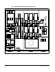
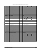
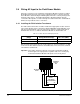
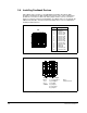
Figure 3.3 – Drive I/O Connections (TB4)
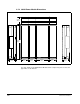
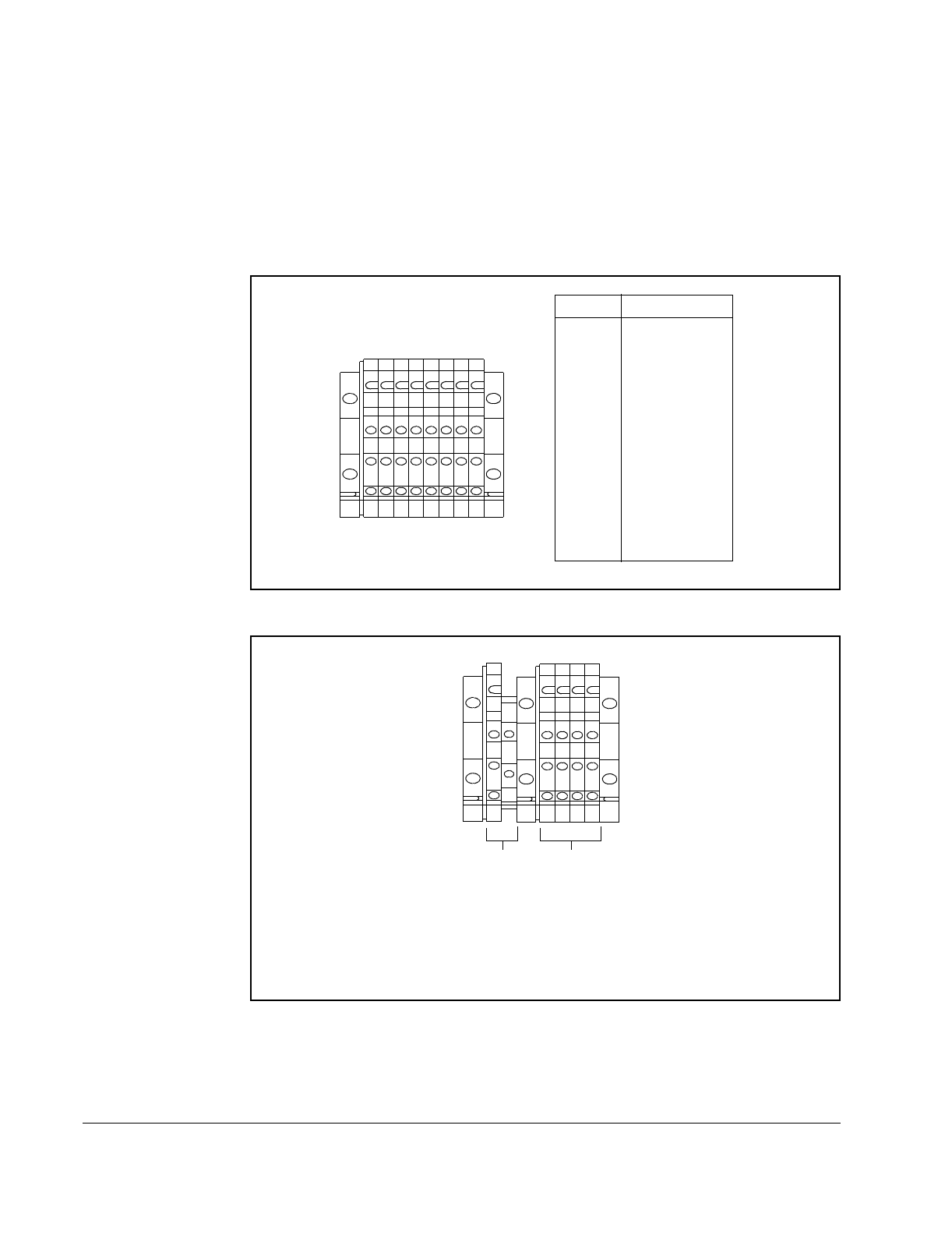
Figure 3.4 – Resolver and Analog Input Connections (TB5)
11
4
1
2
397
8
5
6
1
2
13 15
10 12 14 16
3579
11 13 15
16141210
864
Terminal Signal
1
2
3
4
5
6
7
8
9
10
11
12
13
14
15
16
RPI (HI)
RPI (LO)
AUX IN 1 (HI)
AUX IN 1 (LO)
AUX IN 2 (HI)
AUX IN 2 (LO)
AUX IN 3 (HI)
AUX IN 3 (LO)
AUX IN 4 (HI)
AUX IN 4 (LO)
AUX IN 5 (HI)
AUX IN 5 (LO)
MCR (HI)
MCR (LO)
AUX OUT (HI)
AUX OUT (LO)
TB4
3
2
1
5
6
3
4
1
2
7
8
1
2
3
2468
1357
Analog
Input:
1 (+)
2 (–)
3 GND
Resolver Input:
1 (+) Reference
2 (–) Output
3 (+) Sine
4 (–) Input
5 (+) Cosine
6 (–) Input
TB5
Note:
7,8 Not used