
Manual
Mechanical/Electrical Description
2-19
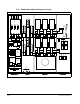
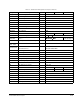
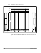
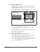
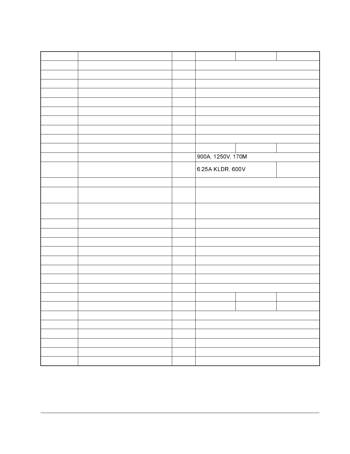
Table 2.6 – 3000A Power Module Symbol-to-Component Reference
Symbol Description Option 460 VAC 575 VAC 660 VAC
A1(+), A2(-) Armature outputs
A11F - A16F Armature pulse transformer PCB
A11R - A16R Armature pulse transformer PCB
ACT1, ACT3 Line current transducer 5000:1
CB11 Circuit breaker ∗ 3000A, SPB-frame
F51 - F53 AC line fuses ∗ 3000A, KRPC
FAN1 Armature bridge fan 1850 CFM
FAN2 Slide-fan 1589 CFM
FAN2-C2 Fan capacitor 40µF
F1, F2, F3 Control branch/feedback PCB fuses 1A KTK 1A KTK 10A A70P
F7 - F12 Armature bridge cell fuses
F14, F15
Control power transformer, primary
fuses
10A, 1500V
Form 101-Type 4
F16 Control power xfmr, secondary fuse 9A KLDR, 600V
F17 - F19,
F27 - F29
Blower motor fuses ∗
FU-A, FU-B
External field isolation
transformer fuses
15A unit: 30A, 700V
60A unit: 100A, 700V
FWD Forward gate connector
REV Reverse gate connector
M1 DC armature contactor 3000A
M11, M12 Blower motor starters ∗
MP Main pilot for pilot relay
PP1 - PP6 Armature power poles
PT2 Control transformer 2kVA
R1 M1 suppressor resistor 1k Ω, 50Ω
SP1 - SP3 Line-to-line MOVs 460J, 320VAC 550J, 385VAC 600J, 420VAC
SP4 Neutral-to-ground MOV 760J, 680VAC 760J, 680VAC 1050J, 750VAC
TB1 Armature feedback terminal block
TB2 Field terminal block
TB3 Control power terminal block
TB4 Drive I/O terminal block
TB5 Resolver feedback terminal block
TB6 Meter ports connector