Distributed Power System SD3100 DC Power Modules 1250A, 1650A, 3000A DC Instruction Manual S-3064
Throughout this manual, the following notes are used to alert you to safety considerations: ! ATTENTION: Identifies information about practices or circumstances that can lead to personal injury or death, property damage, or economic loss. Important: Identifies information that is critical for successful application and understanding of the product.
CONTENTS Chapter 1 Introduction 1.1 Field Power Module ......................................................................................... 1-3 1.2 Standard Features ........................................................................................... 1-3 1.3 Optional Features ............................................................................................ 1-4 1.4 Related Publications ........................................................................................ 1-4 1.
Chapter 4 Maintenance and Troubleshooting 4.1 Recommended Test Equipment.......................................................................4-1 4.2 System Diagnostics..........................................................................................4-2 4.2.1 Power Module Faults .............................................................................4-2 4.2.1.1 Shorted SCR Fault (Bit 0)........................................................4-2 4.2.1.2 AC Line Synchronization Fault (Bit 3)...
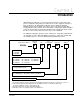
List of Figures Figure 1.1 – SD3100 Catalog Numbering Scheme .................................................. 1-1 Figure 2.1 – SD3100 Power Module System Components ...................................... 2-1 Figure 2.2 – Regulator Assembly ............................................................................. 2-2 Figure 2.3 – Armature Bridge (Non-Regenerative)................................................... 2-5 Figure 2.4 – Armature Bridge (Regenerative)..........................................
IV SD3100 Power Modules
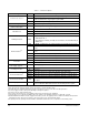
List of Tables Table 1.1 – SD3100 Drive Options ........................................................................... 1-2 Table 1.2 – Field Power Module Part Numbers........................................................ 1-3 Table 1.3 – Distributed Power System DC Drives Documentation........................... 1-4 Table 1.4 – Related Motor Control Center Documentation....................................... 1-5 Table 2.1 – 1250A Configurations .........................................................
VI SD3100 Power Modules
CHAPTER 1 Introduction SD3100 DC Power Modules convert fixed voltage and frequency three-phase AC power to adjustable voltage DC power, which can be used to supply the armature or field of a DC motor. An SD3100 Power Module operates within the AutoMax Distributed Power System (DPS) environment, and is controlled by the AutoMax Programming Executive software.
Table 1.1 – SD3100 Drive Options Drive Option Code 6P Control Power Source1 Dynamic Braking Contactor2 Unit Door Nameplate1 6TB 115 VAC control power, factory wired from 115 VAC control bus to drive unit (1250 and 1650A units only).
1.1 Field Power Module The single-phase Field Power Module is integrally mounted within the SD3100 Power Module to provide the motor field excitation. The Field Power Module is rated 15 or 60 amps at 230/460 VAC. The 15A unit is supplied as standard. The 60A unit is available as an option. The Field Power Module requires a separately-ordered, separately-mounted field isolation transformer.
• 115VAC control bus (90A) • Fiber-optic communication with the Distributed Power System Universal Drive Controller (UDC) module • Drive nameplate - white/black letters 1.3 Optional Features The following features are available as options: • 60 amp Field Power Module • NEMA blower starter • IEC blower starter • Air flow switch • Line suppressor • 115 VAC convenience outlet • Phone jack 1.
Installation of the motor control center (MCC) is described in the manuals listed in table 1.4. Table 1.4 – Related Motor Control Center Documentation Publication Number Description 2100-5.5 Instructions - Receiving, Handling, And Storing Motor Control Centers 2300-5.
1-6 SD3100 Power Modules
CHAPTER 2 Mechanical/Electrical Description Rockwell Automation SD3100 DC Power Modules are built using a Distributed Power System PMI regulator and a high-horsepower silicon-controlled rectifier (SCR) bridge. All components are housed in a NEMA 1 metal enclosure. This chapter provides general information on the mechanical and electrical characteristics of SD3100 Power Modules, followed by specific information on the 1250A, 1650A, and 3000A units.
2.1 Mechanical Overview The SD3100 Power Module is composed of the basic components shown in figure 2.1. These components consist of: • Control components that provide the interface to the AutoMax Distributed Power System and control for the Power Module, and • Power components that convert AC line power to DC power for the motor. 2.1.1 Control Components The control components are contained in the regulator assembly, along with the Field Power Module.
Below the PMI rack is a DPS Parallel Gate Amplifier (PGA), which provides isolation and amplification of the forward and reverse gate drive signals. The Field Power Module is mounted to the left of the PMI and PGA racks. At the top of the assembly are the field isolation transformer fuses and a scaling unit that conditions the armature feedback signals received via terminal block TB1.
Control Power and Field Power Module Tap The first (L1) and third (L3) phase of the incoming power are tapped off and fused to provide single-phase AC power to the primary of the control power transformer and the Field Power Module. Field Isolation Transformer A user-supplied field isolation transformer must be installed on the AC input of the Field Power Module as described in section 3.4.1 of this manual.
The non-regenerative bridge is shown in figure 2.3. Cell fuses protect the thyristors in the event of a bridge failure. Main Contactor SNUBBER SNUBBER SNUBBER *&& *&& *&& 3-Phase AC Input A1 Armature Voltage *&& SNUBBER SNUBBER SNUBBER *&& *&& A2 Figure 2.
The regenerative bridge, shown in figure 2.4, allows the bridge to direct regenerated power back onto the incoming lines. Main Contactor *&& *&& *&& SNUBBER SNUBBER SNUBBER *&& *&& A1 *&& 3-Phase AC Input Armature Voltage *&& *&& *&& SNUBBER SNUBBER SNUBBER *&& *&& *&& A2 Figure 2.
• Gate Coupler Cards Gate coupler cards amplify the gate signal pulses from the DC Power Technology module to trigger the SCRs. In addition, these cards provide gate driver isolation from the control circuits in the PMI rack. • Main DC Contactor The main DC contactor is used to isolate the DC motor armature and to interrupt the DC current to the motor armature. Coil voltage to the contactor is controlled by contacts from the pilot relay. 2.1.2.
The two anti-parallel SCR power bridges in a regenerative Power Module control the direction of motor rotation and the direction of torque, in both forward (motoring) and reverse (regenerating) directions. The regenerative Power Module allows for regeneration of power into the AC line under the condition of an overhauling load. Field Power Module Operation of the Field Power Module is programmed and controlled in the UDC module in the AutoMax rack and the PMI Processor in the PMI rack.
2.3 1250A Power Module Description Table 2.1 – 1250A Configurations Input Voltage (VAC) Output HP 460 700-750 575 750-900 660 700-1000 The 1250A Power Module is supplied in the configurations shown in table 2.1. The 1250A Power Module has the following features: • The 1250A Power Module uses twelve SCRs (regenerative) or six SCRs (non-regenerative) in the armature bridge to convert the 3-phase AC input to a DC output. The SCRs are built into a heatsink assembly that is cooled by the bridge fan.
2.3.
Table 2.
2.3.2 1250A Power Module Dimensions 20 inches (508 mm) 91.5 inches (2324 mm) 20 inches (508 mm) 20 inches (508 mm) 35 inches (889 mm) 20 inches (508 mm) 20 inches (508 mm) Figure 2.6 – 1250A Power Module Dimensions For other details on the 1250A Power Module and its components, please refer to the appendices of this manual.
2.4 1650A Power Module Description Table 2.3 – 1650A Configurations Input Voltage (VAC) Output HP 460 800-1000 575 1000-1250 660 1250 The 1650A Power Module is supplied in the configurations shown in table 2.3. The 1650A Power Module has the following features: • The 1650A Power Module uses twelve SCRs (regenerative) or six SCRs (non-regenerative) in the armature bridge to convert the 3-phase AC input to a DC output. The SCRs are built into a heatsink assembly that is cooled by the bridge fan.
2.4.
Table 2.
2.4.2 1650A Power Module Dimensions 20 inches (508 mm) 91.5 inches (2324 mm) 20 inches (508 mm) 20 inches (508 mm) 35 inches (889 mm) 20 inches (508 mm) 20 inches (508 mm) Figure 2.8 – 1650A Power Module Dimensions For other details on the 1650A Power Module and its components, please refer to the appendices of this manual.
2.5 3000A Power Module Description Table 2.5 – 3000A Configurations Input Voltage (VAC) Output HP 460 1250-1750 575 1500-2250 660 1500-2500 The 3000A Power Module is supplied in the configurations shown in table 2.5. The 3000A Power Module has the following features: • The 3000A Power Module uses twelve SCRs in the armature bridge to convert the 3-phase AC input to a DC output. The SCRs are built into a heatpipe assembly that is cooled by the bridge fan.
2.5.
Table 2.
2.5.2 3000A Power Module Dimensions 20 inches (508 mm) 91.5 inches (2324 mm) 20 inches (508 mm) 20 inches (508 mm) 20 inches (508 mm) 35 inches (889 mm) 20 inches (508 mm) 20 inches (508 mm) Figure 2.10 – 3000A Power Module Dimensions For other details on the 3000A Power Module and its components, please refer to the appendices of this manual.
CHAPTER 3 Installation Guidelines ! ATTENTION: Only qualified personnel familiar with the construction and operation of this equipment and the hazards involved should install, adjust, operate, or service this equipment. Read and understand this manual and other applicable manuals in their entirety before proceeding. Failure to observe this precaution could result in severe bodily injury or loss of life.
3.2 Physically Installing the Power Module ! ATTENTION: The Power Module is at line voltage when connected to incoming AC power. Disconnect, lock out, and tag all incoming power to the drive before performing the following procedures. Failure to observe this precaution could result in severe bodily injury or loss of life. To move and position the unit at your site, follow the instructions given in publication 2100-5.5, titled Instructions - Receiving, Handling, And Storing Motor Control Centers.
3.3.2 Making an Input Entry Hole If your Power Module has an extra input bay installed, proceed as follows. If your Power Module will have a top-hat enclosure over the disconnect bay, mount the top-hat enclosure before continuing. To make an input entry hole, select the ideal hole placement (within the constraints shown in figure 3.1), then perform the steps that follow. Cabinet Width 20.00" 1.25" The width allowed is 2.28 inches shorter than your cabinet's width, as shown.
3.4 Wiring AC Input to the Field Power Module AC power connections to the single-phase Field Power Module are made to terminal block TB2 at the bottom left of the control compartment. Phase control for the Field Power Module is determined by the PMI Regulator, which also controls phasing for the armature power devices. The Field Power Module’s AC input terminals must be connected to AC input lines L1 and L3 through an isolation transformer. Terminal block TB2 has been provided for these connections. 3.4.
3.5 Wiring the Motor To wire DC power to the motor, you will need to do the following: • select appropriate wires for the armature and field lines • connect the motor armature and motor field to the Power Module Refer to your motor’s installation manual for additional information. 3.5.1 Selecting Wires for the Armature and Field Lines ! ATTENTION: The user is responsible for conforming with all applicable local, national, and international codes.
3.6 Installing Feedback Devices All feedback devices interface to the SD3100 Power Module through the PMI Regulator. Terminal blocks TB4 and TB5 at the bottom of the control compartment provide the connections for drive I/O, analog input, and the resolver, as shown in figures 3.3 and 3.4. Selection and installation of feedback devices is described in the PMI Rack and Modules instruction manual (S-3008). Please refer to S-3008 when installing feedback devices.
3.7 Meter Port Connections Terminal block TB6 at the bottom of the control compartment contains four analog output ports, as shown in figure 3.5. Each port can be connected to a separate analog device (e.g., a meter or other data-logging device). The meter port output circuit is described in the PMI Rack and Modules instruction manual (S-3008). Meter port configuration is described in the Drive Configuration and Programming instruction manual (S-3006).
Note that the TE signal ground is not used by the SD3100 drive’s control components, but may be used by other drives in the lineup. Figure 3.6 shows the typical grounding of the SD3100 drive. SD3100 Drive Enclosure Control Xfmr X2 To control components on other drives TE PE To Bldg Steel Motor Ground Rod or Grid (only one grounding point per system) Figure 3.6 – SD3100 Grounding 3.
CHAPTER 4 Maintenance and Troubleshooting ! ATTENTION: Equipment is at line voltage when AC power is connected to the Power Module. All phases of the AC power line and control power must be disconnected from the Power Module before it is safe to touch any internal parts of this equipment. Failure to observe this precaution could result in severe bodily injury or loss of life.
The Power Module may be checked with an ohmmeter for continuity and grounds. Do not test the Power Module or associated circuitry with a megohmmeter (megger). Disconnect all leads to the motor if the motor is to be ground-checked with a megger. Failure to follow proper procedure when using a megger may cause damage to the Power Module. 4.2 System Diagnostics Operation of the Power Module is monitored by the PMI Processor.
4.2.1.3 Instantaneous Overcurrent Fault (Bit 4) LED indicator: EXT FLT UDC Error Code: 1004 The armature current feedback value is greater than the Max Current Limit value (plus 75%) entered as a configuration parameter. The system will immediately go idle when this fault is detected. 4.2.1.4 Conduction Timeout Fault (Bit 5) LED indicator: N/A UDC Error Code: 1005 Discontinuous conduction has not been detected within 2 seconds of CML_RUN (register 100/1100, bit 0) being turned off. 4.2.1.
4.2.2.3 Synchronization Loss Fault Avoided Warning (Bit 3) The system has continued to operate through a temporary loss of AC line voltage. If the AC line voltage is missing for more than 2 seconds, the system will immediately go idle and set bit 3 in register 202/1202 (AC Line Synchronization fault). 4.2.2.4 Current Reference Limit Warning (Bit 4) The current reference has exceeded the value entered as the Max Current Limit configuration parameter. 4.2.2.
• Bridge fan and bridge fan door filter • Slide-in Fan • Power fuses • Power fuse assembly • AC input line fuses • Snubber assembly 4.3.2 PMI Regulator The PMI modules and the PMI rack are serviced by removing the damaged modules or by replacing the complete PMI rack. The PMI rack is attached by four retaining screws through its backplane and a ground lead to the panel ground.
4.3.4.2 Replacing Field Power Module Components Field Power Module components, including the gate driver PC board, snubber PC board, and field clamp assembly, can be replaced. Replacement part numbers are listed in Appendix C. Due to the complexity of alignment, however, it is recommended that the Field Power Module be returned to Rockwell for repair and/or replacement of components.
APPENDIX A Technical Specifications A.1 General Specifications The following specifications apply to the 1250, 1650, and 3000A Power Modules: • AC Input Frequency Range: 48 to 62 Hz • AC Input Voltage Tolerance: ±10% • Overload Capability: 150% maximum DC bus current for 60 seconds 200% for 10 seconds following continuous operation • Overload Duty Cycle: 1 minute out of 20 minutes at rated load and temperature • Ambient Operating temperature: 0 to 40° C (32 to 104° F).
A.2 1250A Power Module Specifications The following specifications apply to the 1250A Power Module. Height Width Depth Shipping Weight MCC Sections Operating Sound Level 91.5” (2324 mm)1 75” (1905 mm) 20” (508 mm) 2500 lbs (1134 kg) 3 83 dB, wt. A 1. Note that the height of the 1250A Power Module includes a 1.5”-high base channel. Table A.
Power Dissipation The 1250A Power Module dissipates power proportionally to the armature current, as shown in figure A.2. Heat Dissipation (W) Armature Current (A) Figure A.2 – Power Dissipation vs. Armature Current (1250A Power Module) Circuit Breaker Settings The 1250A Power Module has a 1200A N-frame circuit breaker with a 1200A plug. The circuit breaker should be set as shown in figure A.3.
AC Input Busbars The 1250A Power Module is normally supplied with two AC input busbars per phase, as shown in figure A.4. Note that if the AC line fuse option is selected, the 1250A Power Module is supplied with the 1650A unit’s busbars. See figure A.7. Bus Dimensions 1.69" 0.250" 0.87" 0.563" Diameter 1.750" Bus Arrangement 4 connections are available for each phase Phase 1 (L1) Phase 2 (L2) Phase 3 (L3) Figure A.
A.3 1650A Power Module Specifications The following specifications apply to the 1650A Power Module. Height Width Depth Shipping Weight MCC Sections Operating Sound Level 91.5” (2324 mm)1 75” (1905 mm) 20” (508 mm) 2500 lbs (1134 kg) 3 83 dB, wt. A 1. Note that the height of the 1650A Power Module includes a 1.5”-high base channel. Table A.
Power Dissipation The 1650A Power Module dissipates power proportionally to the armature current, as shown in figure A.5. Heat Dissipation (W) Armature Current (A) Figure A.5 – Power Dissipation vs. Armature Current (1650A Power Module) Circuit Breaker Settings The 1650A Power Module has a 1600A R-frame circuit breaker with a 1600A plug. The circuit breaker should be set as shown in figure A.6.
AC Input Busbars The 1650A Power Module has two AC input busbars per phase, as shown in figure A.7. These busbars are also used in the 1250A Power Module with the AC line fuse option. Bus Dimensions 0. 83 1.844 0.250 0.88 0.563 Diameter 1.750 Bus Arrangement 8 connections are available for each phase Phase 1 (L1) Phase 2 (L2) Phase 3 (L3) Figure A.
A.4 3000A Power Module Specifications The following table of specifications applies to the 3000A Power Module Height Width Depth MCC Sections Shipping Weight Operating Sound Level 91.5” (2324 mm)1 95” (2413 mm) 20” (508 mm) 4 3500 lbs (1588 kg) 82 dB, wt. A 1. Note that A 20”-high tophat assembly (which mounts over the disconnect bay), is included with each 3000A Power Module. Table A.
Power Dissipation The 3000A Power Module dissipates power proportionally to the armature current, as shown in figure A.8. Heat Dissipation (W) Armature Current (A) Figure A.8 – Power Dissipation vs. Armature Current (3000A Power Module Circuit Breaker Settings The 3000A Power Module has a 3000A SPB-frame circuit breaker. The circuit breaker should be set as shown in figure A.9.
AC Input Busbars The 3000A Power Module has a busbar arrangement allowing up to twelve connections per phase, as shown in figure A.10. Bus Dimensions 0. 88 1.938 0.188 1.938 0.88 1.750 0.625 Diameter Bus Arrangement 12 connections are available for each phase Phase 1 (L1) Phase 2 (L2) Phase 3 (L3) Figure A.
A.5 Air Baffle Layouts ! ATTENTION: Guards are designed to direct airflow in the drive and to prevent injury. Ensure that the guards are in place when operating the drive. Failure to observe this precaution may result in bodily injury. Important: Air baffles are designed to distribute air to cool drive components.
Baffle Baffle Guards Figure A.
A.6 Field Power Module Specifications Ambient Conditions • Storage temperature: -40 to 85° C (-40 to 185° F) • Operating temperature: 0 to 40° C (32 to 104° F) • Humidity: 5 to 95%, non-condensing • Altitude: Up to 1000 meters (3300 feet) without derating output power. For every 91.4 meters (300 feet) above 1000 meters, derate the output current 1%. Enclosure • Enclosed chassis with all circuits covered and protected. Cooling • Convection cooled.
A-14 SD3100 Power Modules
APPENDIX B Schematics CB11 3-Phase AC Input L1 1L1 L2 1L2 L3 1L3 F17 M11 OL11 DC MOTOR AC BLOWER MOTOR (T1) F18 (T2) F19 F27 F28 (T3) M12 OL12 DC MOTOR AC BLOWER MOTOR (T1) (T2) F29 (T3) Figure B.
B-2 TB3 .... ... 7 5 5 5 TB10(1-3) 3 1 SCR FAN FAN1 20 4 .... ...
Figure B.
B-4 5 5 TB10(1-3) 3 1 SCR FAN FAN1 20 4 TB3 .... ... 6 54 L2 LINE L1 FILTER L1 L2 L2 LINE LOAD 115 VAC A2 AC LINE & DC ARM SIGNALS 47 45 TB1 A1 SNUBBER A12F L1 12 G(W) K(R) A14F (8) OPT. M1 AUX. (6) OPT. M1 AUX.
Figure B.
B-6 19 3 1 5 5 (X1) 3 380VAC 2 L3A SCR FAN FAN1 115VAC 20 (X2) 4 F3 1A SP2 J 283 L2 LINE L1 FILTER L1 L2 L2 LINE LOAD SNUBBER AC LINE & DC ARM SIGNALS A12F L2 L1 12 G(W) K(R) A14F A14R G(W) K(R) (R)H1 (W)H2 (8) OPT. M1 AUX. (6) OPT. M1 AUX.
Schematics COSINE OUTPUT (STATOR) SINE OUTPUT (STATOR) REFERENCE INPUT (ROTOR) S4 S2 S3 S1 R2 (–) (+) (–) (+) (+) R1 (–) 6 5 4 3 2 1 EXTERNAL DEVICE (IF USED) (IF USED) MOTOR THERMOSTAT 7 8 FIBER OPTIC COMM. LINK FROM UDC CARD INDUSTRIAL DUTY BRUSHLESS RESOLVER DRIVEN BY MOTOR 5 TFU 1.
B-8 SD3100 Power Modules
APPENDIX C Replacement Parts C.1 Regulator Assembly Please refer to the following instruction manuals for replacement parts information: Component PMI Rack and Modules Parallel Gate Amplifier Rack and Modules Manual Number S-3008 S-3045 C.
C.3 Spare Parts Kits Current Code1 460 VAC 575 VAC 660 VAC R,S,T 2300-SPB01A 2300-SPB01A 2300-SPB02A 1 PCB with 2 sets of fuses Air Flow Switch PCB (Option 14AFL) R,S 2300-SPP01A 2300-SPP01A 2300-SPP01A 1 PCB with 0.5A power supply T 2300-SPP02A 2300-SPP02A 2300-SPP02A 1 PCB with 1.
INDEX A AC input busbars 1250A Power Module, A-4 1650A Power Module, A-7 3000A Power Module, A-10 connecting AC input wires to, 3-3 Air baffles, A-11 to A-12 Altitude derating chart, A-1 Analog input connections (TB5), 3-6 Armature power components, 2-4 to 2-7 bridge components, 2-6 to 2-7 B conduction timeout, 4-3 instantaneous overcurrent, 4-3 loss of field, 4-3 shorted SCR, 4-2 Feedback devices, 3-6 Field isolation transformer, 3-4 Field Power Module AC line input fuses, 4-5 component replacement, 4-5
Maintenance and troubleshooting, 4-1 to 4-6 component replacement, 4-4 to 4-6 faults, 4-2 to 4-3 Field Power Module, 4-5 PMI rack and modules, 4-5 recommended test equipment, 4-1 to 4-2 system diagnostics, 4-2 to 4-4 warnings, 4-3 to 4-4 Mechanical description, 2-2 to 2-7 Meter port connections, 3-7 Motor control center documentation, 1-5 Motor installation, 3-5 N component reference, 2-19 configurations, 2-17 description, 2-17 dimensions, 2-20 schematics, B-6 to B-7 technical specifications, A-8 to A-10
DIF Documentation Improvement Form Use this form to give us your comments concerning this publication or to report an error that you have found. For convenience, you may attach copies of the pages with your comments. After you have completed this form, please return it to: Rockwell Automation RGA (Technical Publications) 25001 Tungsten Road Cleveland, Ohio 44117 Fax: 216.266.
Rockwell Automation / 24703 Euclid Avenue / Cleveland, Ohio 44117 / (216) 266-7000 Printed in U.S.A.