
Owner manual

SD3000 PLUS DC Drive Regulator 7
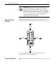
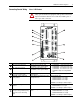
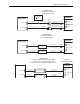
Checking the Indicators
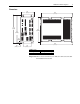
GP
COM OK
FDBK OK
LP
P.M. FLT
RPI
OK
EXT. FLT
XMT
RCV
L1
L2
MCR
AUX IN 1
AUX IN 2
AUX IN 3
AUX IN 4
AUX IN 5
AUX OUT
FWD - GATES
REV - GATES
120VAC
EXT GATE P/S
FUSE TYPE
250VAC
3AG 7A
RESOLVER
FEEDBACK
DRIVE
I/O
METER
PORTS
ARM
FDBK
FIELD
PLUS
DRIVE CONTROL
Engineered by
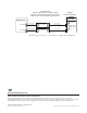
SD3000
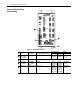
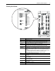
GP
COM OK
FDBK OK
LP
P.M. FLT
RPI
OK
EXT. FLT
XMT
RCV
MCR
AUX IN 1
AUX IN 2
AUX IN 3
AUX IN 4
AUX IN 5
AUX OUT
Engineered by
LED Indicates
GP Gate Power is present
LP Logic Power is present
OK The drive regulator has passed its internal power-up diagnostic tests. After
power-up this LED will turn off if the internal “watchdog timer” fault occurs.
P.M. FLT Shorted SCR, Field Current Feedback too low or too high.
EXT. FLT Loss of AC Line Synchronization, AC Line Missing, Instantaneous Over-Current
(IOC), Over-speed, User program has initiated the illumination of the LED.
COMM OK Drive Comm is active and synchronized.
FDBK OK The SD3000 Plus is receiving feedback from the resolver and no resolver feedback
faults have been detected. If the LED is off, one of the following faults may have
occurred:
• Feedback Loss Fault - armature voltage has exceeded 40% of the rated value
and speed feedback has been less than 5% of motor base speed
• Broken Wire Fault - a resolver sine or cosine signal is missing
RPI The Run Permissive Input (RPI) is energized.
AUX IN 1 Auxiliary Input 1 is energized. This input usually indicates the status of the
M-Contactor.
AUX IN 2 Auxiliary Input 2 is energized. This input often indicates the status of an inverting
fault circuit breaker.
AUX IN 3 Auxiliary Input 3 is energized. This input often indicates the status of the Power
Module’s airflow switch.
AUX IN 4 Auxiliary Input 4 is energized. This input often indicates the status of the motor
thermal switch.
AUX IN 5 Auxiliary Input 5 is energized.
AUX OUT Auxiliary Output is energized.