
Owner manual


Trusted™ Bridge Module 8161
Issue 2 Feb 10 PD-8161 11
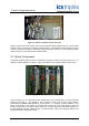
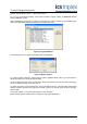
Figure 5 Trusted™ controller chassis rear view
Figure 5 shows a four socket version of the T8312 Expander Interface Adaptor with a TC-301-01 cable
attached, which connects to a Trusted™ expander chassis. The Expander Interface Adapter has four
or seven connections available to individual Trusted™ Expander chassis or to the Triguard controller
chassis using the TC-322-02 Interface Cable Assembly.
2.3 Module Configuration
The Bridge module requires minimum configuration, namely the setting of Unit ID jumpers 0 to 3 to
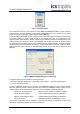
define the chassis address to Trusted™. These are situated on the Triguard chassis as shown here.
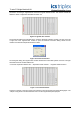
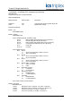
Figure 6 Chassis Address Jumpers
Unit ID jumpers 0,1,2,3 represent the binary address bits 1,2,4 & 8 respectively. A removed jumper
signals a binary digit ‘1’. The address is set to between 2 and 8. On the first Triguard chassis
(containing the SC300E Bridge Modules), remove jumper 1 to represent Trusted™ address '2' (as
shown in the picture). The jumpers on all three sets must be set to the same address. Leave the
jumpers as they were on the other Triguard chassis. It is usual to attach the chassis with address 2 to
the first Expander Interface Adapter socket, for both Trusted™ chassis and Triguard chassis. This
makes the software configuration easier.