Trusted™ PD-8161 Trusted™ / SC300E Bridge Module Introduction The SC300E Bridge presents a new opportunity to combine the SC300E Triguard I/O structure with the latest processing and communications features of Trusted™. Combining the two products will enable Triguard users to benefit from features such as 3-3-2-0 Processor fault tolerance, IEC 1131 programming suite, Ethernet networks, OPC, Ethernet peer to peer and remote diagnostics.
Trusted™ Bridge Module 8161 Issue Record Issue Number Date Revised by Technical Check Authorised by Modification 1 Apr 08 A Holgate N Owens P Stock Initial Issue 2 Feb 10 A Holgate N Owens P Stock TC-322 details Issue 2 Feb 10 PD-8161 2
Trusted™ Bridge Module 8161 Table of Contents 1. Description......................................................................................................................................7 1.1 Overview.........................................................................................................................................7 1.2 Power Distribution ..........................................................................................................................8 1.
Trusted™ Bridge Module 8161 6. Specifications ...............................................................................................................................43 Figures Figure 1 Block Diagram showing interface between Trusted™ system and Triguard I/O...................... 7 Figure 2 8161 Bridge Module ................................................................................................................. 9 Figure 3 TC-322-02 Interface Cable assembly.................................
Trusted™ Bridge Module 8161 Precautionary Information WARNING Warning notices call attention to the use of materials, processes, methods, procedures or limits which must be followed precisely to avoid personal injury or death. CAUTION Caution notices call attention to methods and procedures which must be followed to avoid damage to the equipment.
Trusted™ Bridge Module 8161 Associated Equipment Part Number Product Name T8042 SC300E Toolset Library Description Adds equipment definitions for SC300E modules to the Trusted™ Toolset TC-322-02 CS300/SC300E Interface Cable Assembly To connect between Trusted™ Expander Interface Adaptor and SC300E Controller Chassis TC-325-02 SC300E Interface Cable Connector Card To attach TC-322-02 cable to SC300E Controller Chassis Table 1 Bridge Module Associated Equipment Issue 2 Feb 10 PD-8161 6
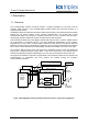
Trusted™ Bridge Module 8161 1. Description 1.1 Overview The SC300E Bridge enables connection between a Triguard SC300E I/O sub system and the Trusted™ TMR Processor. Three SC300E Bridge modules replace the three MPP modules in a Triguard primary chassis. The Bridge module has a fast serial ("Hotlink") interface that transfers command and response packets between the two product families via the Trusted™ Expander Bus.
Trusted™ Bridge Module 8161 1.2 Power Distribution Each of the Bridge modules is powered from dual redundant 5.4V dc via the backplane from the chassis PAC or PDC dual power supplies. 1.3 Communication Busses 1.3.1 The Trusted™ to SC300E Primary Chassis Communication between the Trusted™ Expander Interface Module and the SC300E Primary Chassis is via one of a possible four or seven triplicated two-way interface cables.
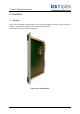
Trusted™ Bridge Module 8161 2. Installation 2.1 Module Each of the three Bridge modules replaces one of the Triguard MPP processors. Figure 2 shows the module. The replacement must be carried out with the system offline. The modules consist of a single PCB assembly.
Trusted™ Bridge Module 8161 2.2 TC-322-02 Interface Cable assembly The interface cable connects from the Trusted™ Interface Adaptor T8312 to an identical 12 way socket on the interface cable connector card.
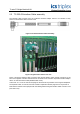
Trusted™ Bridge Module 8161 Figure 5 Trusted™ controller chassis rear view Figure 5 shows a four socket version of the T8312 Expander Interface Adaptor with a TC-301-01 cable attached, which connects to a Trusted™ expander chassis. The Expander Interface Adapter has four or seven connections available to individual Trusted™ Expander chassis or to the Triguard controller chassis using the TC-322-02 Interface Cable Assembly. 2.
Trusted™ Bridge Module 8161 3. Application All Triguard I/O modules are configured using the IEC1131 application Toolset provided with Trusted™. This configuration requires entries in the System Configuration (System.INI) for the chassis and modules and their hardware operational parameters, and also in the workbench I/O connection table, for software settings and data connection. 3.
Trusted™ Bridge Module 8161 The first chassis to be created is a 8161. This includes the bridge modules in place of the Triguard processors. Choose type Triguard 8161 and select a logical chassis number. This chassis number will define the switch configuration described in section 2.3. Figure 9 Triguard main chassis The chassis should then be allocated to the Trusted™ Expander Interface module. Left-click on the left or right end of the Triguard 8161 chassis to open the Chassis Connection dialog.
Trusted™ Bridge Module 8161 Figure 12 Jumper Setting This chassis then links into the extension chassis MBB and MRB04XM. MBB is a local extension chassis linked to the main chassis by ribbon cables. MRB04XM is also a local chassis but it provides remote connection via fibre optic cables to slave chassis MRB04XS. To add an MBB or MRB04XM chassis, right click again on the background and select the chassis type.
Trusted™ Bridge Module 8161 < Trusted™ expander Interface slot> - - - e.g. 1-2-2-3-1 in the above example, if the system consists of a 8161 chassis, an MRB04XM chassis and an MRB04XS chassis. Having added all the chassis in the system, the next step is to insert modules. For each module, rightclick on the appropriate chassis slot. Select the module from the list.
Trusted™ Bridge Module 8161 3.2 Board Definitions There are no restrictions in the order of the boards set out in the connection table except in cases where TM117-DMX (64-Channel De-Multiplexed Driver) termination cards are configured in the system. These have to be defined before any SC300E I/O modules are specified. The DMX cards are driven from the Trusted™ serial communications module. It is also general convention to specify the Trusted™ main processor at the head of the connection table.
Trusted™ Bridge Module 8161 3.2.1 Module – 8161 (Bridge Module) DESCRIPTION This definition provides module status for a Logical Triguard 8161 primary chassis expansion interface module. The logical module accounts for the 3 physical modules FCR-A, FCR-B and FCR-C. OEM PARAMETERS: OEM parameter Valid numbers Description CHASSIS 2-29 Logical chassis number allocated to the primary Triguard chassis in which the 8161 modules are placed.
Trusted™ Bridge Module 8161 3.2.2 Module – MBB (Bus interface Module) DESCRIPTION This definition provides module status for a logical Triguard MBB local chassis expansion module. The logical module accounts for the 3 physical modules FCR-A, FCR-B and FCR-C. OEM PARAMETERS: OEM parameter Valid numbers Description CHASSIS 2-29 Logical chassis number allocated to the local secondary Triguard chassis in which the MBB modules are placed.
Trusted™ Bridge Module 8161 3.2.3 Module – mai32lad (0-5V; analogue input Module) DESCRIPTION This definition will open a single MAI32LAD. OEM PARAMETERS OEM parameter Valid numbers Description CHASSIS SLOT 2-29 1-10 Logical chassis and slot number where the MAI32LAD is located.
Trusted™ Bridge Module 8161 3.2.4 Module – mai32mad (0-10V; analogue input Module) DESCRIPTION This definition will open a single MAI32MAD. OEM PARAMETERS OEM parameter Valid numbers Description CHASSIS SLOT 2-29 1-10 Logical chassis and slot number where the MAI32MAD is located.
Trusted™ Bridge Module 8161 3.2.5 Module – mai32nad (0-20Ma; analogue input Module) DESCRIPTION This definition will open a single MAI32NAD. OEM PARAMETERS OEM parameter Valid numbers Description CHASSIS SLOT 2-29 1-10 Logical chassis and slot number where the MAI32NAD is located.
Trusted™ Bridge Module 8161 3.2.6 Module – mai32pad (0-40Ma; analogue input Module) DESCRIPTION This definition will open a single MAI32PAD. OEM PARAMETERS OEM parameter Valid numbers Description CHASSIS SLOT 2-29 1-10 Logical chassis and slot number where the MAI32PAD is located.
Trusted™ Bridge Module 8161 3.2.7 Module – mao04nnd (0-22Ma; analogue output Module) DESCRIPTION This definition will open a single MAO04NND. OEM PARAMETERS OEM parameter Valid numbers Description CHASSIS SLOT 2-29 1-10 Logical chassis and slot number where the MAO04NND is located.
Trusted™ Bridge Module 8161 Word 4 Fault flags, 0=healthy 1=fault bit 0-2 Logic supply power fail fault (ABC, bit0=A, bit2=C) bit 3-5 Reserved bit 6 Field power fail fault bit 7 Output discrepancy error bit 8-15 Reserved RACK 3: (FAULTS) 1 INTEGER input Word 1 LFD errors, channels 1-4 (bit 0 = channel 1) Issue 2 Feb 10 PD-8161 24
Trusted™ Bridge Module 8161 3.2.8 Module – mdi32bis (24v; digital input Module) DESCRIPTION This definition will open a single MDI32BIS. OEM PARAMETERS OEM parameter Valid numbers Description CHASSIS SLOT 2-29 1-10 Logical chassis and slot number where the MDI32BIS is located.
Trusted™ Bridge Module 8161 3.2.9 Module – mdi32fis (120v; digital input Module) DESCRIPTION This definition will open a single MDI32FIS. OEM PARAMETERS OEM parameter Valid numbers Description CHASSIS SLOT 2-29 1-10 Logical chassis and slot number where the MDI32FIS is located.
Trusted™ Bridge Module 8161 3.2.10 Module – mdi32gis (48v; digital input Module) DESCRIPTION This definition will open a single MDI32GIS. OEM PARAMETERS OEM parameter Valid numbers Description CHASSIS SLOT 2-29 1-10 Logical chassis and slot number where the MDI32GIS is located.
Trusted™ Bridge Module 8161 3.2.11 Module – mdi64bns (24v simplex; digital input Module) DESCRIPTION This definition will open a single MDI64BNS. OEM PARAMETERS OEM parameter Valid numbers Description CHASSIS SLOT 2-29 1-10 Logical chassis and slot number where the MDI64BNS is located.
Trusted™ Bridge Module 8161 RACK 3: (FAULTS) 8 INTEGER inputs Word 1 Discrepancy errors, channels 1-16 (bit 0 = channel 1) Word 2 Discrepancy errors, channels 17-32 (bit 0 = channel 17) Word 3 Discrepancy errors, channels 33-48 (bit 0 = channel 33) Word 4 Discrepancy errors, channels 49-64 (bit 0 = channel 49) Word 5 LFD errors, channels 1-16 (bit 0 = channel 1) Word 6 LFD errors, channels 17-32 (bit 0 = channel 17) Word 7 LFD errors, channels 33-48 (bit 0 = channel 33) Word 8 LFD errors, channels 49-64 (bi
Trusted™ Bridge Module 8161 3.2.12 Module – mdo16fns (120v; digital output Module) DESCRIPTION This definition will open a single MDO16FNS. OEM PARAMETERS OEM parameter Valid numbers Description CHASSIS SLOT 2-29 1-10 Logical chassis and slot number where the MDO16FNS is located.
Trusted™ Bridge Module 8161 Word 4 Fault flags, 0=healthy 1=fault bit 0-2 Logic supply power fail fault (ABC, bit0=A, bit2=C) bit 3-5 Field supply power fail fault (ABC) bit 6 Bias supply 1 power fail fault bit 7 Bias supply 2 power fail fault bit 8 Logic supply power fail fault bit 9-10 Reserved bit 11-13 Drive supply power fail fault (ABC) bit 14 Field supply power fail fault bit 15 Over temperature fault RACK 3: (FAULTS) 1 INTEGER inputs Word 1 LFD errors, channels 1-16 (bit 0 = channel 1) Issue 2 Feb 1
Trusted™ Bridge Module 8161 3.2.13 Module – mdo16gns (48v; digital output Module) DESCRIPTION This definition will open a single MDO16GNS. OEM PARAMETERS OEM parameter Valid numbers Description CHASSIS SLOT 2-29 1-10 Logical chassis and slot number where the MDO16GNS is located.
Trusted™ Bridge Module 8161 Word 4 Fault flags, 0=healthy 1=fault bit 0-2 Logic supply power fail fault (ABC, bit0=A, bit2=C) bit 3-5 Field supply power fail fault (ABC) bit 6 Bias supply 1 power fail fault bit 7 Bias supply 2 power fail fault bit 8 Logic supply power fail fault bit 9-10 Reserved bit 11-13 Drive supply power fail fault (ABC) bit 14 Field supply power fail fault bit 15 Over temperature fault RACK 3: (FAULTS) 1 INTEGER inputs Word 1 LFD errors, channels 1-16 (bit 0 = channel 1) Issue 2 Feb 1
Trusted™ Bridge Module 8161 3.2.14 Module – mdo32bns (24v; digital output Module) DESCRIPTION This definition will open a single MDO32BNS. OEM PARAMETERS OEM parameter Valid numbers Description CHASSIS SLOT 2-29 1-10 Logical chassis and slot number where the MDO32BNS is located.
Trusted™ Bridge Module 8161 Word 4 Fault flags, 0=healthy 1=fault bit 0-2 Logic supply power fail fault (ABC, bit0=A, bit2=C) bit 3-5 Field supply power fail fault (ABC) bit 6 Bias supply 1 power fail fault bit 7 Bias supply 2 power fail fault bit 8 Logic supply power fail fault bit 9-10 Reserved bit 11-13 Drive supply power fail fault (ABC) bit 14 Field supply power fail fault bit 15 Over temperature fault RACK 3: (FAULTS) 2 INTEGER inputs Word 1 LFD errors, channels 1-16 (bit 0 = channel 1) Word 2 LFD err
Trusted™ Bridge Module 8161 3.2.15 Module – mhb44ind (Pulse-in/analogue output Module) DESCRIPTION This definition will open a single MHB44IND. OEM PARAMETERS OEM parameter Valid numbers Description CHASSIS SLOT 2-29 1-10 Logical chassis and slot number where the MHB44IND is located.
Trusted™ Bridge Module 8161 Word 4 Fault flags, 0=healthy 1=fault bit 0-2 Logic supply power fail fault (ABC, bit0=A, bit2=C) bit 3-5 Reserved bit 6 Field power fail fault bit 7 Output discrepancy error bit 8-15 Reserved RACK 4: (FAULTS) 3 INTEGER inputs Word 1 Discrepancy errors bits 0-3 PI channels 1-4 (bit 0 = channel 1) Word 2 LFD errors bits 0-3 PI channels 1-4 (bit 0 = channel 1) bits 4-7 AO channels 1-4 (bit 4 = channel 1) Issue 2 Feb 10 PD-8161 37
Trusted™ Bridge Module 8161 3.2.16 Module – mrb01xs (remote slave Module) DESCRIPTION This definition provides module status for a logical Triguard MRB01XS remote slave chassis expansion module. The logical module accounts for the 3 physical modules FCR-A, FCR-B and FCR-C. OEM PARAMETERS: OEM parameter Valid numbers Description CHASSIS 2-29 Logical chassis number allocated to the remote slave Triguard chassis in which the MRB01XS modules are placed.
Trusted™ Bridge Module 8161 3.2.17 Module – mrb04xm (remote master Module) DESCRIPTION This definition provides module status for a logical Triguard MRB04XM remote master chassis expansion interface module. The logical module accounts for the 3 physical modules FCR-A, FCR-B and FCR-C. OEM PARAMETERS: OEM parameter Valid numbers Description CHASSIS 2-29 Logical chassis number allocated to the secondary Triguard chassis in which the MRB04XM modules are placed.
Trusted™ Bridge Module 8161 4.
Trusted™ Bridge Module 8161 4.1 Front Panel Indicators and Controls 4.1.1 Tx & Rx Indicators Flashing amber LEDs indicate active transmit and receive communications on the Expander Bus. 4.1.2 Health Indicator A steady green LED indicates a fault-free Bridge module; an extinguished LED indicates a fault. 4.1.3 On-Line Indicator and Switch Raising and releasing the on/off-line switch momentarily takes the module off-line, which is mirrored by the steady On/Off state of the amber On-Line LED.
Trusted™ Bridge Module 8161 5. Fault Finding and Maintenance The Trusted™ TMR Processor provides fault monitoring, self test and diagnostics functions. Fault Detection within a Trusted™ / SC300E system can be categorised into four regions Trusted™ TMR Processor and Expander Hardware SC300E Bridge Hardware SC300E I/O Hardware User Application Using current Trusted™ methods for detection of faults, the TMR Processor can monitor for failures up to the Expander section.
Trusted™ Bridge Module 8161 6. Specifications Supply Voltage 5.4V DC ± 5% Heat Dissipation 3W max Operating Temperature (convection cooling) 0°C to 60ºC (32°F to 140°F) Storage Temperature -40°C to 100ºC (-40°F to 212°F) Operating Humidity 5 to 95% RH, non-condensing Vibration 10 to 500 Hz peak to peak 1g Shock Operating:11ms, ½ sine wave 15g Height: 400 mm (15.7 ins) Width: 27 mm (1.1 ins) Depth: 404 mm (15.9 ins) Weight (approx) 900g (2.0 lbs.