Distributed Power System SB3000 Synchronous Rectifier &RQILJXUDWLRQ DQG 3URJUDPPLQJ Instruction Manual S-3034
Throughout this manual, the following notes are used to alert you to safety considerations: ! ATTENTION: Identifies information about practices or circumstances that can lead to personal injury or death, property damage, or economic loss. Important: Identifies information that is critical for successful application and understanding of the product.
CONTENTS Chapter 1 Introduction Chapter 2 Configuring the UDC Module, Regulator Type, and Parameters 2.1 Adding a UDC Module ..................................................................................... 2-1 2.2 Entering the Drive Parameters ........................................................................ 2-2 2.2.1 Power Module Parameter Entry ............................................................ 2-4 2.2.2 PMI Meter Port Selection ....................................................
Appendix A SB3000 Drive Register Reference ........................................................................... A-1 Appendix B SB3000 Local Tunable Variables............................................................................. B-1 Appendix C SB3000 Control Algorithm........................................................................................ C-1 Appendix D Status of Data in the AutoMax Rack After a STOP_ALL Command or STOP_ALL Fault .................................................
List of Figures Figure 2.1 – Power Module Parameter Entry Screen ............................................... 2-4 Figure 2.2 – PMI Meter Port Selection Screen ......................................................... 2-6 Figure 3.1 – UDC Task Scan.................................................................................. 3-48 Figure 3.2 – Nth Scan Interrupts............................................................................. 3-50 Figure 4.1 – UDC Task Scan.................................
IV SB3000 Drive Configuration and Programming
List of Tables Table 1.1 – Related Publications .............................................................................. 1-1 Table 2.1 – Restricted Drive Type Combinations ..................................................... 2-2 Table 2.2 – Supported SB3000 Power Modules....................................................... 2-5 Table 2.3 – PMI Meter Port Parameters ................................................................... 2-7 Table 3.1 – UDC Module Configuration Views and Registers .......
VI SB3000 Drive Configuration and Programming
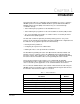
CHAPTER 1 Introduction This manual describes the configuration and programming necessary to control the SB3000 Synchronous Rectifier. SB3000 Rectifiers operate within the AutoMax™ Distributed Power System (DPS) environment. They are controlled through coordination among: • Tasks written by the programmer for the AutoMax Processor. • Tasks written by the programmer for the Universal Drive Controller (UDC) module.
Additional information about using the SB3000 Synchronous Rectifier is found in the wiring diagrams, prints, and other documentation shipped with each drive system. Always consult the documentation shipped with your drive system for specific information about installing, operating, and maintaining your drive.
CHAPTER 2 Configuring the UDC Module, Regulator Type, and Parameters ! ATTENTION: Only qualified personnel familiar with the construction and operation of this equipment and the hazards involved should install, adjust, operate, or service this equipment. Read and understand this manual and other applicable manuals in their entirety before proceeding. Failure to observe this precaution could result in severe bodily injury or loss of life.
Step 4. Select a product type and a regulator (control) type for both drive A and drive B. See the following section for regulator selection rules. The remainder of this chapter assumes that you have selected an SB3000 voltage regulator. Step 5. Select OK to add the UDC module to the rack and return to the Rack Configuration screen. Rules for Configuring/Selecting Drives for the UDC Module 1.
Step 1. Zoom into the UDC module. The Power Module Interface (PMI) screen will be displayed. You can also access this screen directly by double-clicking the UDC module. This screen shows either one or two PMI diagrams, depending upon the information you previously entered. One diagram will be shown for drive A and one for drive B, if used. Each PMI diagram will show a Flex I/O port (Port 0) and the analog or digital Flex I/O modules that are connected to the PMI. Initially, no Flex I/O is connected.
Step 3. Use the Configure parameters option to access the Parameter Entry screens. Assuming you are configuring an SB3000 Synchronous Rectifier, you can access two screens: Power Module Data and Meter Port selection. These screens are described in detail in the following sections. Note that the AutoMax slot number of the UDC module is shown at the top of the screens. The screens prompt for specific information depending upon the item that is being configured. Step 4.
• AC Line Frequency (Hz) (Range: 25, 50, or 60, +/- 2%) The AC line frequency parameter is the nominal frequency being supplied to the rectifier. There is no default value. You must select one of the three values from the list. Power Module • Part Number The screen displays a list of the supported SB3000 Power Modules. Selection is made based upon the current rating of the Power Module being configured. The current ratings displayed are the rated RMS currents with no overload and 40° C ambient temperature.
2.2.2 PMI Meter Port Selection PMI Meter ports 1 and 2 are dedicated to driving two standard meters supplied with the SB3000 Rectifier. Meter port 1 drives the DC bus output current meter. Meter port 2 drives the AC input current meter. Meter ports 3 and 4 are not used on standard SB3000 systems, but can be programmed to operate custom display meters. See figure 2.2. A DC bus voltmeter is hardwired directly to the SB3000 DC bus output terminals. Figure 2.
The following variables are available for output on the PMI D/A ports: Table 2.
2.3 Generating the Drive Parameter Files and Printing Drive Parameters When you have completed all of the drive parameter screens, you can select “Close” to leave the Parameter Entry Screens and return to the master rack diagram with the UDC module selected. Zoom out or select the Exit command from the Configure menu to return to the System Configurator. You can generate the drive parameter files by using the steps that follow. Step 1.
CHAPTER 3 Configuring the UDC Module’s Registers ! ATTENTION: Only qualified personnel familiar with the construction and operation of this equipment and the hazards involved should install, adjust, operate, or service this equipment. Read and understand this manual and other applicable manuals in their entirety before proceeding. Failure to observe this precaution could result in severe bodily injury or loss of life.
• The Feedback Registers view is used to configure the feedback registers that display the current status of the drive. These registers are written to by the PMI. • The Application Registers Updated Every Scan view is used to configure the application registers that are used for the passing of application-specific control and status data between an AutoMax Processor and the UDC module on every scan. This register range is shared by drive A and drive B.
3.1 Register and Bit Reference Conventions Used in this Manual Register numbers are shown using the convention A/B, where A is the drive A register number and B is the drive B register number. Note that the Interrupt Status Control registers and the Application registers are the same for both drive A and drive B. Register descriptions are shown in the following format: Register Name Register Numbers Sug. Var.
Table 3.1 – UDC Module Configuration Views and Registers View 3-4 Register Range Described in Section: Rail I/O Drive A: 0- 11 Drive B: 12-23 3.2 UDC/PMI Communication Status Registers Drive A: 80-89 Drive B: 1080-1089 3.3 Command Registers Drive A: 100-108 Drive B: 1100-1108 3.4 Feedback Registers Drive A: 200-222 Drive B: 1200-1222 3.5 Application Registers Updated Every Scan 300-599 3.6 Application Registers Updated Every Nth Scan 1300-1599 3.
Table 3.2 – UDC Module Dual Port Memory Register Organization.
3.2 Rail I/O Port Registers (Registers 0-23) The Rail I/O Port 0 and Port 1 views are used to assign variable names to the rail ports on the PMI. If you have no hardware attached to these ports, do not configure these registers. All of the Rail data for PMI A and PMI B is combined into one section of the dual port memory. Refer to table 3.3. Note that the usage of each register is a function of the type of Rail that is configured.
Table 3.3 – Rail I/O Port Registers Rail Type and Signal 2 Input3 2 Output Digital I/O4 Input 0 Output 0 Digital Output 1 Input 1 Output 1 N/A Port 0 - Channel 2 Output 2 Input 2 Input 2 N/A 15 Port 0 - Channel 3 Output 3 Input 3 Input 3 N/A 4 16 Port 0 - Fault Register (Tables 3.4 - 3.6) 5 17 Port 0 - Check Bit Fault Count Register (Tables 3.4 - 3.
Table 3.
3.3 UDC/PMI Communication Status Registers (Registers 80-89/1080-1089) The UDC/PMI Communication Status Registers display the status of the fiber-optic communications between the UDC module and the PMI. Two consecutive errors will be indicated by a communication fault, and the drive will stop. Refer to register 202/1202, bit 15, for more information. Note that the communication status registers are for system use only and can only be monitored.
UDC Module Communication Status Register (Continued) 80/1080 DMA Format Error The DMA Format Error bit is set if the length of the received message does not match the length encoded in the message itself. Bit 4 Hex Value: Sug. Var. Name: Access: UDC Error Code: LED: 0010H N/A Read only N/A N/A Transmitter Underrun The Transmitter Underrun bit is set if the USC reports a transmit first-in, first-out underrun. Bit 5 Hex Value: Sug. Var.
UDC Module Communication Status Register (Continued) 80/1080 Multiplexed Data Verification Failure The Multiplexed Data Verification Failure bit is set if data which is multiplexed into command/feedback messages does not verify correctly. Bit 9 Hex Value: Sug. Var.
UDC Module CRC Error Count Register This register contains the number of messages with CRC errors received by the UDC module from the PMI. 82/1082 Sug. Var. Name: Units: Range: Access: UDC Module Format Error Count Register This register contains the number of messages with format errors received by the UDC module from the PMI. N/A Counts N/A Read only 83/1083 Sug. Var.
PMI Communication Status Register (Continued) 84/1084 Overrun Error The Overrun Error bit is set if the USC reports a receive first-in, first-out overrun. Bit 3 Hex Value: Sug. Var. Name: Access: UDC Error Code: LED: 0008H N/A Read only N/A N/A DMA Format Error The DMA Format Error bit is set if the length of the received message does not match the length encoded in the message itself. Bit 4 Hex Value: Sug. Var.
PMI Communication Status Register (Continued) 84/1084 Multiplexed Data Verification Failure The Multiplexed Data Verification Failure bit is set if data multiplexed into command/feedback messages does not verify. Bit 9 Hex Value: Sug. Var. Name: Access: UDC Error Code: LED: 0200H N/A Read only N/A N/A Invalid PMI Start Operating System Address The Invalid PMI Start Operating System Address bit is set by the PMI if the operating system is not within the allocated operating system address area.
PMI Communication Status Register (Continued) 84/1084 PMI Operating System Overflow into Stack Memory The PMI Operating System Overflow into Stack Memory bit is set by the PMI if the loading of the PMI operating system will overrun the PMI stack memory area. Hex Value: Sug. Var. Name: Access: UDC Error Code: LED: Bit 15 8000H N/A Read only N/A N/A This condition will cause the loading of the PMI operating system to fail.
UDC Module Fiber-Optic Link Status Register This register shows the current operating state of the fiber-optic link to the PMI. The lower byte (bits 0-7) shows the actual link status while the upper byte (bits 8-15) shows whether the communication taking place is synchronized or not. 88/1088 Sug. Var. Name: Units: Range: Access: N/A N/A N/A Read only If the lower byte is equal to: xx01H:the UDC module is waiting for a request from the PMI for an operating system.
3.4 Command Registers (Registers 100-199/1100-1199) The Command Registers view is used to configure command registers. These registers are used for command data sent to the PMI by the UDC module at the end of every scan of the UDC Processor. Note that the bits in these registers (except bit 15 in register 100/1100) are used to command action only and do not indicate the status of the action commanded. The feedback registers (registers 200/1200 to 299/1299) are provided for this purpose.
Drive Control Register (Continued) ! 100/1100 ATTENTION: The motor must be disconnected before the bridge test is run. Failure to observe this precaution could result in damage to, or destruction of, the equipment. Fault Reset Bit 8 The Fault Reset bit is set and reset to clear the Drive Fault register, 202/1202. After a drive fault is latched, the Drive Fault register must be cleared before the drive can be re-started. Hex Value: Sug. Var.
Drive Control Register (Continued) 100/1100 Enable Parallel Power Module B This bit is set to enable the bridge test in the second power module in a parallel power module configuration. Bit 2 in this register must be set first and the pre-charge contactor must close before this bit can be set. Bit 11 Hex Value: Sug. Var. Name: Access: UDC Error Code: LED: 0800H PPM_ENB@ Read only N/A N/A See the description of bit 2 above and G for more information about performing the bridge test.
I/O Control Register 101/1101 The I/O Control Register contains the bits that control the EXT FLT LED on the PMI Processor, the auxiliary output on the Resolver & Drive I/O module, and the loopback test. External Fault LED The External Fault LED command bit is set by the application task to turn on the EXT FLT LED on the PMI Processor. Bit 2 Hex Value: Sug. Var.
Voltage Reference Register The value in the Voltage Reference register is the desired DC bus voltage. This value is the main input into the voltage loop on the PMI Processor. The loop is enabled in register 100/1100, bit 0. 102/1102 Sug. Var. Name: Units: Range: Access: VDC_REF% Volts See text Read/Write The minimum value is 1.414 times the RMS value of the AC line voltage plus 10%. The maximum value is 875V. If the value is outside this range, register 203/1203, bit 4 (WRN_RIL@) will be set.
3.5 Feedback Registers (Registers 200-299/1200-1299) The Feedback Registers view is used to configure the feedback registers that display the current status of the drive. These registers are updated by the PMI Processor and sent to the UDC module over the fiber-optic link before every scan of the UDC task. The status of these registers is retained after a Stop All. Drive Status Register 200/1200 The bits in the Drive Status register indicate the current state of the Synchronous Rectifier.
Drive Status Register (Continued) 200/1200 Power Factor Current In Limit The Power Factor Current in Limit bit is set if the power factor current is being limited by the PMI to keep the current minor loop from saturating. Bit 3 Hex Value: Sug. Var. Name: Access: UDC Error Code: LED: 0008H IPF_LMT@ Read only N/A N/A Line Synchronized The Line Synchronized bit is set when the PMI Processor is synchronized to the AC line.
Drive Status Register (Continued) 200/1200 CCLK Synchronized The CCLK Synchronized bit is set when the CCLK in the UDC module is synchronized with CCLK in the Rectifier’s PMI Processor. Bit 14 Hex Value: Sug. Var. Name: Access: UDC Error Code: LED: 4000H CCLK_OK@ Read only N/A N/A This bit is equal to zero if CCLK is not turned on in the AutoMax rack or if there have been two consecutive instances when CCLK is not synchronized after the application task has turned CCLK on.
I/O Status Register (Continued) ! 201/1201 ATTENTION: Do not use the RPI input on the SB3000 Rectifier’s Resolver & Drive I/O module as a method of shutting off the Rectifier. Turning this input off stops the Rectifier’s power devices from firing. However, the emitter-collector diodes in these power devices will still conduct and will continue to feed the load inverter if input power is on. Failure to observe this precaution could result in damage to, or destruction of, the equipment.
I/O Status Register (Continued) 201/1201 115 VAC Auxiliary Input 5 The Auxiliary Input 5 bit reflects the status of the 115 VAC auxiliary input 2 on the Resolver & Drive I/O module in the Rectifier’s PMI rack. When the input signal is present, this bit is set. Bit 5 Hex Value: Sug. Var. Name: Access: UDC Error Code: LED: Pre-Charge Feedback The Pre-charge Feedback bit reflects the status of the Rectifier’s pre-charge contactor. The PMI sets this bit when the contactor is closed.
Drive Fault Register (Continued) 202/1202 DC Bus Overcurrent Fault The DC Bus Overcurrent Fault bit is set if DC bus current exceeds 125% of the Rectifier’s rated DC bus current. Bit 1 Hex Value: Sug. Var. Name: Access: UDC Error Code: LED: 0002H FLT_DCI@ Read only 1020 P.M. FLT Instantaneous Overcurrent Fault The Instantaneous Overcurrent Fault bit is set if a power device overcurrent or shoot-through fault occurs. Bit 3 Hex Value: Sug. Var.
Drive Fault Register (Continued) 202/1202 Charge Fault The Charge Fault bit is set if either of the following has occurred: Bit 6 Hex Value: Sug. Var. Name: Access: UDC Error Code: LED: 0040H FLT_CHG@ Read only 1024 EXT FLT and P.M. FLT • the pre-charge contactor did not close when commanded to by the PMI Processor, or • the contactor opened without being commanded to do so. Overtemperature Fault The Overtemperature Fault bit is set if the fault level thermal switch in the power module opens.
Drive Fault Register (Continued) 202/1202 PMI Power Supply Fault The PMI Power Supply Fault bit is set if the power supply for the Rectifier’s PMI rack is not operating properly. Bit 12 Hex Value: Sug. Var. Name: Access: UDC Error Code: LED: PMI Read/Write Fault The PMI Read/Write Fault bit is set if a PMI Processor read or write operation fails. Bit 13 Hex Value: Sug. Var.
Drive Warning Register 203/1203 The warnings indicated by the Drive Warning register cause no action by themselves. Any resulting action is determined by the application task. The user must ensure that the AutoMax application task monitors register 203/1203 and takes appropriate action if any of these conditions occurs. If a warning condition is detected, the corresponding bit is latched until the Warning Reset bit (bit 9) of the Drive Control register (register 100/1100) is set.
Drive Warning Register (Continued) 203/1203 Reference In Limit Warning The Reference in Limit Warning bit is set if the VDC reference (register 102/1102).is less than the minimum or greater than the maximum allowed, where: Bit 4 Hex Value: Sug. Var. Name: Access: UDC Error Code: LED: 0010H WRN_RIL@ Read only N/A N/A Minimum = 1.1 * 1.414 * AC line VRMS Maximum = 875 volts In Bridge Test mode, this bit is used by the bridge test to indicate an illegal test code.
Drive Warning Register (Continued) 203/1203 Power Module Overload Warning The Power Module Overload Warning bit is set if the continuous current rating of the Rectifier is exceeded for a period of approximately 5 minutes and does not decrease and maintain the continuous rating for at least 45 minutes. Bit 9 Hex Value: Sug. Var.
Drive Warning Register (Continued) 203/1203 Rail Communication Warning The Rail Communication Warning bit is set if a rail communication problem occurs and is logged in registers 4, 10, 16, or 22. Bit 13 Hex Value: Sug. Var. Name: Access: UDC Error Code: LED: 2000H WRN_RAL@ Read only N/A I/O FLT Refer to tables 3.4, 3.5, and 3.6 for further information.
Power Device Status Register 204/1204 The bits in the Power Device Status register indicate the status of the power devices in Power Module A (the Rectifier’s main power module). When multiple power modules are connected in parallel, status registers 220/1220 and 221/1221 are used for Power Modules B and C, respectively. If an IOC (overcurrent) fault is detected, the associated phase upper and lower status bits are set.
Power Device Status Register (Continued) 204/1204 Phase W-Lower IOC A The Phase W-Lower A status bit is set if an IOC or DSAT fault occurs in Power Module A’s phase W, lower power device. Bit 5 Hex Value: Sug. Var. Name: Access: UDC Error Code: LED: 0020H W_LOA@ Read only N/A N/A Intelligent Power Module A The Intelligent Power Module A bit is set to indicate that a DSAT (shoot-through) fault has occurred in Power Module A.
Power Device Status Register (Continued) 204/1204 Phase W Loss The Phase W Loss bit is set if AC line phase W is lost. Bit 11 Hex Value: Sug. Var. Name: Access: UDC Error Code: LED: 0400H W_PL@ Read only N/A N/A Over Temperature A The Over Temperature A bit is set if an over temperature fault or warning occurs in Power Module A. Bit 12 Hex Value: Sug. Var.
Interlock Register 205/1205 The Interlock tests are executed whenever bit 0 or bit 2 of register 100/1100 is set. The first problem detected will cause the corresponding bit in the Interlock Register to set. If any of these bits are set, it will prevent the voltage loop from running.
Interlock Register (Continued) 205/1205 Rising Edge Required The Rising Edge Required bit is set if a rising edge is not detected on a command bit in register 100/1100. Bit 4 Hex Value: Sug. Var. Name: Access: UDC Error Code: LED: 0010H IC_RISE@ Read only N/A N/A This interlock bit will be set if the application task has set the Fault Reset bit (register 100/1100, bit 8) but has not cleared and then re-enabled any command bits.
Interlock Register (Continued) 205/1205 VDC Not Allowed The VDC Not Allowed bit is set if the bridge test is requested and VDC is greater than 10V. Bit 11 Hex Value: Sug. Var. Name: Access: UDC Error Code: LED: DC Bus Voltage (Volts) Register The DC Bus Voltage register contains the measured DC bus voltage. The displayed value is scaled in volts. 206/1206 Sug. Var. Name: Units: Range: Access: DC Bus Current (Amps) Register The DC Bus Current (Amps) register contains the measured current in the DC bus.
VAR Feedback (Volts * Amps) Register The VAR Feedback register contains the volt-amperes reactive (VARS) produced by the Rectifier in response to the reference in register 103/1103. The value is scaled in VARS divided by 1000. For example, 10,000 VARS (10 KVARS) is displayed as 10. 211/1211 Sug. Var. Name: Units: Range: Access: Iq Feedback (Amps) Register The Iq Feedback register contains the Iq component of the current feedback. Iq is the current that supplies the DC bus.
Parallel Power Module B Status Register 220/1220 The bits in the Parallel Power Module B Status register indicate the status of the power devices in Power Module B. This register is used only when two or more power modules are connected in parallel. If an IOC (overcurrent) fault is detected, the associated phase upper and lower status bits are set. If a phase DSAT (shoot-through) fault is detected, the associated phase status bits are set and the Intelligent Power Module bit, IPUB@, is set.
Parallel Power Module B Status Register (Continued) 220/1220 Phase W-Lower IOC B The Phase W-Lower B status bit is set if an IOC or DSAT fault occurs in Power Module B’s phase W, lower power device. Bit 5 Hex Value: Sug. Var. Name: Access: UDC Error Code: LED: 0020H W_LOB@ Read only N/A N/A Intelligent Power Module B The Intelligent Power Module B bit is set to indicate that a DSAT (shoot-through) fault has occurred in Power Module B. Bit 6 Hex Value: Sug. Var.
Parallel Power Module B Status Register (Continued) 220/1220 Phase U Current Sharing B The Phase U Current Sharing B bit is set if a Power Module B is not carrying its share of the phase U current. Bit 13 Hex Value: Sug. Var. Name: Access: UDC Error Code: LED: 2000H U_SHRB@ Read only N/A N/A Phase V Current Sharing B The Phase V Current Sharing B bit is set if Power Module B is not carrying its share of the phase V current. Bit 14 Hex Value: Sug. Var.
Parallel Power Module C Status Register (Continued) 221/1221 Phase W-Upper IOC C The Phase W-Upper C status bit is set if an IOC or DSAT fault occurs in Power Module C’s phase W, upper power device. Bit 2 Hex Value: Sug. Var. Name: Access: UDC Error Code: LED: 0004H W_UPC@ Read only N/A N/A Phase U-Lower IOC C The Phase U-Lower IOC CC status bit is set if an IOC or DSAT fault occurs in Power Module C’s phase U, lower power device. Bit 3 Hex Value: Sug. Var.
Parallel Power Module C Status Register (Continued) 221/1221 GDI Fault C The GDI Fault C bit is set if a fault is detected in the power supply of Power Module C’s Gate Driver Interface module. Bit 7 Hex Value: Sug. Var. Name: Access: UDC Error Code: LED: 0080H GDIC@ Read only N/A N/A Charge Fault C The Charge Fault C bit is set if a charge bus time-out fault occurs in Power Module C (refer also to register 202/1202, bit 6). Bit 8 Hex Value: Sug. Var.
Diagnostic Fault Code Register 222/1222 The Diagnostic Fault Code register displays an error code to help diagnose the cause of a problem reported in other registers. Note that this register is available for monitoring only. It cannot be referenced in an application task. Sug. Var.
Diagnostic Fault Code Register (Continued) 222/1222 Run Time AC Power Technology Module Faults (Continued) Code 22 Fault A/D interrupt overrun Description/Action An interrupt from the ACPTM was detected before the previous interrupt was processed. Replace the ACPTM, PMI rack, and/or Power Supply. 23 Gate power test 1 fault Gate power is on when the MCR is off and Gate Enable is on. Replace the ACPTM. 24 Gate power test 2 fault Gate Power is on when MCR is off and Gate Enable is on.
3.6 Application Registers (Registers 300-599, Every Scan) (Registers 1300-1599, Every Nth Scan) ! ATTENTION: If you use double integer variables, you must implement a software handshake between the transmitter and the receiver to ensure that both the least significant and the most significant 16 bits have been transmitted before they are read by the receiving application program. Failure to observe this precaution could result in bodily injury or damage to equipment.
The registers within this range (1300-1599) that are written to by a UDC task are updated by the UDC operating system from its local memory to dual port memory at the end of the scan that occurs before the Nth scan (N-1). At that time, an interrupt will be generated by the UDC operating system to indicate that new data has been written to the dual port memory. Refer to the 2000-series registers for more information on interrupts.
Figure 3.2 – Nth Scan Interrupts 3-50 SB3000 Drive Configuration and Programming Scan 2 Scan 3 Scan 4 Input A Write “every scan" registers that are outputs from task A Latch “every scan" registers that are inputs to task B Write “Nth scan" registers that are outputs from both tasks A and B Write “every scan” registers that are outputs from task B. Run B Output B Write “every scan” registers that are outputs from task A UDC operating system generates interrupt to AutoMax Processor.
3.7 UDC Module Test I/O Registers (Registers 1000-1017) This view is used to configure the UDC module’s Test Switch Inputs Register and the Meter Port Setup Registers. 3.7.1 UDC Module Test Switch Inputs Register (Register 1000) This view is used to configure the register that displays the status of the test switches and LED indicators on the UDC module. Writing to this register will not change the state of the LEDs. The status of this register is retained during a Stop All.
UDC Test Switch Inputs Register (Continued) 1000 COMM A OK LED The COMM A OK LED bit shows the status of the COMM A OK LED on the UDC module ( 0 = OFF; 1 = ON). Bit 9 Hex Value: Sug. Var. Name: Access: UDC Error Code: LED: Drive A Fault LED The Drive A Fault LED bit shows the status of the Drive A Fault LED on the UDC module ( 0 = OFF; 1 = ON). Bit 10 Hex Value: Sug. Var.
3.7.2 UDC Module Meter Port Setup Registers (Registers 1000-1017) Registers 1001-1017 are used to configure the UDC module’s meter ports. This configuration determines what variables from the UDC module’s dual port memory are to be displayed on the meter ports at the end of the UDC scan. At system power-up, the output values of the ports are reset to zero. To map a UDC variable to a specific meter port at power-up, refer to table 3.3 and use the following procedure.
3.7.2.1 Resolution of Meter Port Data For meter ports, the output values will be clamped at the outside (+/-10V) limits. Note that if you select to display a data range that is narrower than the actual range of the data, your output values will not change until the value returns to within the range you selected to display. In other words, data is being updated at the rate described above, but the actual output voltage may not change.
Meter Port 1 UDC Module Meter Port 1 Register Number Register UDC register number (0 - 2044) to be mapped to meter port 1. 1002 Sug. Var. Name: Units: Range: Access: N/A N/A N/A Read/Write UDC Module Meter Port 1 Bit Number Register Bit number of the UDC register specified in register 1002 that is to be mapped to port 1. Enter a value of 100 (bit 00) to 115 (bit 15) as required. Enter a value of zero if all of the register’s bits are to be displayed. 1003 Sug. Var.
Meter Port 2 UDC Module Meter Port 2 Register Number Register UDC register number (0 - 2044) to be mapped to meter port 2. 1006 Sug. Var. Name: Units: Range: Access: N/A N/A N/A Read/Write UDC Module Meter Port 2 Bit Number Register Bit number of the UDC register specified in register 1002 that is to be mapped to port 2. Enter a value of 100 (bit 00) to 115 (bit 15) as required. Enter a value of zero if all of the register’s bits are to be displayed. 1007 Sug. Var.
Meter Port 3 UDC Module Meter Port 3 Register Number Register UDC register number (0 - 2044) to be mapped to meter port 3. 1010 Sug. Var. Name: Units: Range: Access: N/A N/A N/A Read/Write UDC Module Meter Port 3 Bit Number Register Bit number of the UDC register specified in register 1002 that is to be mapped to port 3. Enter a value of 100 (bit 00) to 115 (bit 15) as required. Enter a value of zero if all of the register’s bits are to be displayed. 1011 Sug. Var.
Meter Port 4 UDC Module Meter Port 4 Register Number Register UDC register number (0 - 2044) to be mapped to meter port 4. 1014 Sug. Var. Name: Units: Range: Access: N/A N/A N/A Read/Write UDC Module Meter Port 4 Bit Number Register Bit number of the UDC register specified in register 1002 that is to be mapped to port 4. Enter a value of 100 (bit 00) to 115 (bit 15) as required. Enter a value of zero if all of the register’s bits are to be displayed. 1015 Sug. Var.
3.8 Interrupt Status and Control Registers (Registers 2000-2047) This view is used to configure registers that control the operation of interrupts to a task on an AutoMax Processor in the rack and to enable CCLK in the rack. These registers are used for Drive A and B. Only one UDC task should write to these registers. Note that the status of these registers is not retained after a Stop All. Interrupt Status Control Register The Interrupt Status Control register contains the following information.
Interrupt Status Control Registers (Continued) 2000 CCLK Counting Bit 5 Hex Value: Sug. Var. Name: Access: UDC Error Code: LED: 0010H N/A Read only N/A N/A Enable CCLK on the Multibus Backplane CCLK must be enabled in the rack for the UDC module to execute its task(s) and communicate synchronously with the PMI. Bit 6 Hex Value: Sug. Var. Name: Access: UDC Error Code: LED: 0001H N/A Read/Write N/A N/A Only one module per rack should enable CCLK.
Scans Per Interrupt Register The Scans Per Interrupt register contains the number of times a UDC task is to be scanned between updates of the Nth scan application registers. 2001 Sug. Var. Name: Units: Range: Access: SPI% N/A See below. Read/Write Note that you must write the desired value to this register before you turn on CCLK. The default value is zero (i.e., not applicable because an interrupt is not being used but is updated each scan). One is a permissible value.
3-62 SB3000 Drive Configuration and Programming
CHAPTER 4 Application Programming for DPS Drive Control ! ATTENTION:Only qualified personnel familiar with the construction and operation of this equipment and the hazards involved should install, adjust, operate, or service this equipment. Read and understand this manual and other applicable manuals in their entirety before proceeding. Failure to observe this precaution could result in severe bodily injury or loss of life.
UDC tasks must be written in the Control Block language, a language designed specifically for drive control. To differentiate them from Control Block tasks written for AutoMax Processors, they must be specified as UDC tasks in the Programming Executive software. Like Control Block tasks on AutoMax Processors, UDC tasks can include a number of BASIC language statements and functions; however, those that allow task suspension or delay are not supported.
All common input values for the UDC task are first read from the dual port memory and then stored in a local buffer in order to have a consistent context for evaluation. The task is then executed. After the task has been executed, the common output values from the UDC task are written from the local memory buffer to dual port memory. The only exception to this pattern are the common variables in the “Nth” scan application register area.
Step 4. SCAN_LOOP block/Enabling CCLK This control block tells the UDC operating system how often to execute the task based on the constant clock (CCLK) signal on the rack backplane. Note that the CCLK signal must be enabled by a task in the rack before any UDC tasks in the rack can b scanned beyond their SCAN_LOOP blocks. Note that CCLK must be enabled again after a STOP ALL in the rack.
Step 6. Motor thermal overload protection Electronic thermal overload protection for SA3100 drives is normally provided by the THERMAL OVERLOAD block. The following briefly describes how the THERMAL OVERLOAD block works, how to program the block, and what adjustments are possible. Each UDC task must contain a THERMAL OVERLOAD block, unless motor thermal overload protection is provided by a hardware device. See J-3676, the Control Block Language instruction manual, for the structure of the block.
Consider an example in which LIM_BAR is defined to be 150% of full load current, THRESHOLD is 114%, and TRIP_TIME is 60 seconds. When I_FDBK is at 100%, CALC_RISE will reach a steady state value of 1000 (1002 / 10). With THRESHOLD at 114%, the trip point for CALC_RISE will be 1300 (1142 / 10). If I_FDBK is at steady state (100%) and then is stepped to 150%, CALC_RISE will integrate up to 1300 in 60 seconds and OVERLOAD will turn on. The OVERLOAD output will stay on until the rise decays to less than 1000.
Like all tunable values in the AutoMax environment, the values of these UDC task tunables are retained through a power loss. Note that the programmer can also define other local tunable variables for application-specific purposes, but that the total number of all local tunables in a UDC task cannot exceed 127. 4.2.2.1 Calculating Local Tunable Values Depending upon the type of local tunable variable, the “CURRENT” value, i.e.
The exchange of command and feedback register data is synchronized through the use of the constant clock signal (CCLK) on the UDC module as described below. CCLK also enables the coordination of all UDCs in a rack because they will all use the same time base for task execution. Note that all UDC modules in a rack are not required to have the same value in the TICKS parameter of the SCAN_LOOP block in both their tasks.
CCLK_OK@ COM_FLT@ RUN_PERM@ Start Permissive Logic RUN_PERM@ Figure 4.2 – Recommended Run Permissive Logic Refer to the individual bit descriptions in this manual for more information. 4.3 AutoMax Processor Task and UDC Task Coordination Recall that all tasks running on AutoMax Processors have access to the UDC dual port registers, but that UDC tasks can only access those common variables that represent registers in their own dual port memory.
Figure 4.3 – Data/Time Flow for UDC Module and PMI 4-10 SB3000 Drive Configuration and Programming Vector * Diagnostics, Communication, Management, etc. 10 msec. (20 ticks) dual port memory application registers in UDC values to control command and AutoMax task writes new *Communication of command and feedback registers between the UDC and PMI synchronized UDC tasks and PMI control algorithms are not synchronized. The vector control algorithm runs, on the average, every 1 msec. 1.
CHAPTER 5 On-Line Operation ! ATTENTION:Only qualified personnel familiar with the construction and operation of this equipment and the hazards involved should install, adjust, operate, or service this equipment. Read and understand this manual and other applicable manuals in their entirety before proceeding. Failure to observe this precaution could result in severe bodily injury or loss of life.
The option “A” for ALL will automatically load the rack (i.e., AutoMax Processor configuration, the drive parameters for all the UDC modules in the rack, and all tasks for the rack, including all UDC tasks). The drive parameters may be loaded to the UDC module in a specified slot or to all UDC modules in the rack. When the drive parameters are loaded, the AutoMax Programming Executive will determine if the drive parameters are compatible with the existing rack configuration.
Deleting UDC Tasks When a UDC application task is deleted, any local variables which were forced are removed from the force table. The task’s error log is also cleared. 5.4 UDC Information Log and Error Log The information log and error log for a UDC task can be displayed by selecting “I” for Info/Log from the ON LINE menu. Refer to the AutoMax Programming Executive instruction manual for the procedure.
5-4 SB3000 Drive Configuration and Programming
APPENDIX A SB3000 Drive Register Reference REGISTER MAP Registers Function 0-23 Analog ch. 0 input over-range 24-79 80-89 System Use Only1 UDC/PMI comm.
FEEDBACK REGISTERS (CONTINUED) A/B 204/1204 Power Device status Bit 0 Phase U -upper A 1 Phase V -upper A 2 Phase W -upper A 3 Phase U -lower A 4 Phase V -lower A 5 Phase W -lower A 6 Power Module A fault 7 GDI fault A 8 Bus charge time-out A 9 Phase U loss 10 Phase V loss 11 Phase W loss 12 Overtemperature A 13 Phase U current sharing A 14 Phase V current sharing A 15 Phase W current sharing A U_UPA@ V_UPA@ W_UPA@ U_LOA@ V_LOA@ W_LOA@ IPUA@ GDIA@ CHGA@ U_PL@ V_PL@ W_PL@ OTA@ U_SHRA@ V_SHRA@ W_SHRA@ 205/1
APPENDIX B SB3000 Local Tunable Variables C_E6% Capacitance The value in this variable selects the capacitance connected to the bus. The value is scaled in microfarads. Units: Default Value: Low Limit: High Limit: Step: µF 32400 32400 97200 1 For a single power unit, assign a value of 32400. For two parallel power units, 64800. For three parallel power units, 97200.
L_E6% Inductance Units: Default Value: Low Limit: High Limit: Step: The value stored in this variable sets the inductance of the Power Module. The value is scaled in microhenries. µH 500 167 500 1 For a single power unit, assign a value of 500. For two parallel power units, 250. For three parallel units, 167. OVT_E0% Overvoltage Warning Threshold A warning is generated (register 203/1203, bit 0) if the DC bus voltage exceeds the value stored in this variable. The value is scaled in volts.
VDC_KD% Voltage Loop Derivative Gain The value in this variable selects the voltage loop derivative gain. This value should normally be set to 0. VDC_WCO% Units: Default Value: Low Limit: High Limit: Step: None 0 0 400 1 Voltage Loop Crossover Frequency The value in this variable selects the desired response of the voltage loop. The higher the value, the more quickly the rectifier responds to a change in voltage reference. The value is entered in radians/second.
B-4 SB3000 Drive Configuration and Programming
APPENDIX C SB3000 Control Algorithm SB3000 Synchronous Rectifiers regulate DC bus voltage using a vector control algorithm. This algorithm, which is executed in the PMI processor, is also referred to as the minor loop. (The major control loop is executed in the AutoMax processor.) The UDC application control task passes the desired DC bus voltage reference command to the PMI Processor in register 102/1102.
C-2 + + Kp = Vml - Wco C Ki = Vml - Wco Vml - A Filter 25% Ki E1 + z-1 Vml_Kd Kp z-1 (Ipf_Ref_E1) (Vdc_Ref_E0) PI_Lmt_E4 (Id_Cmd) (Iq_Cmd) Cnf I_Lmt ∗ 1.414 Software Limit Power Factor Current + – – PI_Lmt_E1 + Min_Vdc_Ref_E0 = Vac_Rms_E0 ∗ 1.414 ∗ 1.1 f(460) = 715 Ramp (Pi_Lmt_E4) (Pi_Lmt_E1) + (Vdc_Fbk_E0) 1000 if (!drv_on||restart) Vdc_Ref_E0 = Vdc_Ramp_E1++/10 Vml_Ff Max_Vdc_Ref_E0 = Max_Volts - 25 =875 Filter 40% – + (Vdc_Ref_E0) (Idc_Fbk_E1) (Cnf.I_Lmt_E1 ∗ 1.
APPENDIX D Status of Data in the AutoMax Rack After a STOP_ALL Command or STOP_ALL Fault AutoMax Processor UDC Module PMI Processor LOCAL tunable variables retained retained retained LOCAL variables retained reset to 0 N/A COMMON memory variables non-volatile are retained; others are reset to 0 N/A N/A I/O variables (including UDC dual port memory inputs retained and updated; outputs are reset to 0 inputs retained and updated; outputs are reset to 0 all I/O is reset to 0 Input values, inc
D-2 SB3000 Drive Configuration and Programming
APPENDIX E SB3000 Pre-Charge Sequencing The SB3000 Synchronous Rectifier System is shown in figure E.1 on the following page. The pre-charge is controlled via a pre-charge contactor, which is under the control of the PMI Processor in the SB3000’s PMI rack. The contactor is mounted separately in the power distribution cabinet. Any faults in contactor operation are reported in UDC registers 202/1202 and 205/1205.
Figure E.
Load Inverter Pre-charge Contactor Requirements ! ATTENTION: The UDC application task must examine the pre-charge status bit (CHG_FB@) regularly. If the status bit turns off, the load inverters must be shut down. If the inverters are not shut down, the precharge resistor may be damaged. Failure to observe this precaution could result in damage to, or destruction of, the equipment. The status of the SB3000 Rectifier pre-charge contactor (CHG_FB@) must be checked by the inverter application tasks.
Control Power On Pre-charge Contactor is Open Pre-charge contactor is closed Report fault (FLT_CHG) No charge faults & Vdc > Vdiode or Test mode active & Vdc < 5V Command pre-charge to close Wait for Pre-charge to Close Pre-charge times out Report fault (FLT_CHG) Pre-charge is closed & in test mode & Vdc < 5V Pre-charge is closed & Vdc > Vdiode Pre-charge Closed - RUN Pre-charge opens Report fault (FLT_CHG) Pre-charge Closed - TEST Vdc < Power Loss Threshold Disable gate Report fault (FLT_CHG) Comman
APPENDIX F Enabling the Voltage Loop ! ATTENTION: The pre-charge contactor for the SB3000 must be closed and the voltage loop must be on (register 200/1200, bit 0) before any load inverters can be put into run. If the SB3000 pre-charge contactor is not closed, running a load inverter will burn up the pre-charge resistors. Failure to observe this precaution could result in damage to, or destruction of, the equipment.
OVT_E0% Power On UVT_E0% Vac ∗ 1.414 VDC_RUN VDC_ON Figure F.
APPENDIX G Performing the Bridge Test Important: This test is normally performed at the factory. It should not be necessary to perform it again unless the power devices or fiber-optic cables are replaced. The bridge test is used to verify gate cabling connections by test firing IGBTs one at a time, cycling through the power module that is enabled. As the IGBTs fire, the LEDs on the corresponding GDI module in the rectifier’s PMI rack will turn on and off in the following order: 1. U- Lower Power Device 2.
Bridge Test Procedure To perform the bridge test: Step 1. Disconnect, lockout, and tag three-phase AC power to the Synchronous Rectifier. Step 2. Ensure that the DC bus is fully discharged. Refer to Appendix H. Step 3. Command the bridge test, using register 100/110, bit 2, and bit 10, 11, or 12, as applicable. Step 4. Verify that the LEDs turn on and off in the order listed. If the LEDs do not turn on and off in the proper order, reconnect the fiber-optic gate cables as shown on the wiring diagrams.
APPENDIX H Discharging the DC Bus ! ATTENTION: DC bus capacitors retain hazardous voltages after input power has been disconnected. After disconnecting input power, wait ten (10) minutes for the DC bus capacitors to discharge. Open the cabinet doors and check the voltage across the DC bus bars, 347 A,B,C (+ bus) and 345 A,B,C (- bus), with an external voltmeter to ensure the DC bus capacitors are discharged before touching any internal components.
H-2 SB3000 Drive Configuration and Programming
INDEX A Access level, 3-3 Application programming, 4-1 to 4-10 AutoMax and UDC task coordination, 4-9 AutoMax tasks, 4-1 calculating local tunable values, 4-7 data/time flow for UDC and PMI, 4-10 local tunable variables, 4-6 to 4-7 recommended run permissive logic, 4-9 typical structure of a UDC task, 4-3 to 4-6 UDC task scan, 4-2 UDC tasks, 4-1 to 4-10 UDC/PMI task communication, 4-7 to 4-10 Application registers, 3-48 to 3-49 AutoMax rack status of data, D-1 B Bit Name, 3-3 Bit Number, 3-3 Bridge test, 3
running UDC tasks, 5-2 stopping UDC tasks, 5-2 UDC information and error logs, 5-3 VAR feedback (volts * amps), 3-40 voltage feedback (volts rms), 3-39 G P Generating drive parameter files, 2-8 H Hex Value, 3-3 I Interrupt status and control registers, 3-59 to 3-61 interrupt status control, 3-59 to 3-60 scans per interrupt, 3-61 Interrupts, 4-3, 4-8 Introduction, 1-1 to 1-2 L LED indicator, 3-3 Local tunable variables, 4-6 to 4-7, B-1 to B-3 calculating local tunable values, 4-7 M Meter ports parame
PMI receive count, 3-15 UDC communication status, 3-9 to 3-11 UDC CRC error count, 3-12 UDC fiber-optic link status, 3-16 UDC format error count, 3-12 UDC receive count, 3-11 UDC transmitted message count, 3-16 V Variable configurator, 3-1 Viewing registers, 3-1 to 3-2 application registers, 3-2 command registers, 3-1 feedback registers, 3-2 interrupt status and control registers, 3-2 Rail I/O, 3-1 UDC module test I/O register, 3-2 Voltage loop, 3-17 enabling, F-1 to F-2 Index turning on VDC_RUN, F-2 W
Index-4 SB3000 Drive Configuration and Programming
DIF Documentation Improvement Form Use this form to give us your comments concerning this publication or to report an error that you have found. For convenience, you may attach copies of the pages with your comments. After you have completed this form, please return it to: Rockwell Automation RGA (Technical Publications) 25001 Tungsten Road Cleveland, Ohio 44117 Fax: 216.266.
Rockwell Automation / 24703 Euclid Avenue / Cleveland, Ohio 44117 / (216) 266-7000 Printed in U.S.A.