
Owner's manual


3-2
Universal Drive Controller Module
Step 4. Insert the module into the desired slot in the rack (refer to section 4.1 for
module restrictions). Use a screwdriver to secure the module into the rack.
Step 5. Use the following procedure to connect a fiber-optic cable (P/N 613613-xxR)
between the UDC module and the PMI:
a. Remove the dust cover caps from the fiber-optic ports on the UDC module
and the PMI.
b. Remove the dust cover caps from the fiber-optic cable’s connectors.
c. Store the dust cover caps in a safe place. The dust cover caps must be
re-installed on the fiber-optic ports and connectors whenever they are
disconnected.
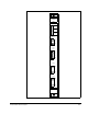
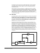
d. Attach the cable’s connectors to the following ports as shown in figure 3.1.
• UDC module XMT port: blue fiber-optic cable
• UDC module RCV port: orange fiber-optic cable
• PMI XMT port: orange fiber-optic cable
• PMI RCV port: blue fiber-optic cable
Note that the fiber-optic cables are color-coded. Typically, the cables are
orange and blue. The cables used in your installation may be of a different
color but they should be installed in the same manner as described here.
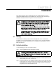
Align the connector’s pin with the slot in the module’s port. See figure 3.2.
Push the connector onto the port. Turn the connector clockwise until it locks
onto the port’s two pins. Refer to the Fiber Optic Cabling instruction manual
(S-3009) for additional information.
!
!