Distributed Power System Universal Drive Controller Module B/M O-57552 Universal Drive Controller Module EM B/M O-57652 Instruction Manual S-3007-3
Throughout this manual, the following notes are used to alert you to safety considerations: ! ATTENTION: Identifies information about practices or circumstances that can lead to personal injury or death, property damage, or economic loss. Important: Identifies information that is critical for successful application and understanding of the product. The thick black bar shown at the margin of this paragraph will be used throughout this manual to indicate new or revised text or figures.
CONTENTS Chapter 1 Introduction 1.1 Related Publications ........................................................................................ 1-2 1.1.1 1567 Power Max™ Documentation....................................................... 1-3 Chapter 2 Mechanical/Electrical Description 2.1 Mechanical Description ................................................................................... 2-1 2.2 Electrical Description ..............................................................................
II Universal Drive Controller Module
List of Figures Figure 1.1 – Typical Hardware Configuration ........................................................... 1-1 Figure 2.1 – Module Faceplate (B/M O-57652) ........................................................ 2-3 Figure 2.2 – Analog Output Circuit (Meter Ports) ..................................................... 2-5 Figure 3.1 – Fiber-Optic Cable Connections ............................................................ 3-3 Figure 3.2 – Fiber-Optic Ports and Connectors ......................
IV Universal Drive Controller Module
List of Tables Table 1.1 – DPS Documentation .............................................................................. 1-2 Table 1.2 – Power Max™ Documentation (Binder S-3040)......................................
VI Universal Drive Controller Module
CHAPTER 1 Introduction The AutoMax™ Universal Drive Controller (UDC) module is used for Distributed Power drive control applications. The Distributed Power System (DPS) is a programmable microprocessor-based control system that is capable of real-time control of AC and DC drives. The UDC module plugs into the backplane of an AutoMax rack and is used to control one or two drives. Both AC and DC drives can be controlled from one UDC module.
1.1 Related Publications The documentation that describes the SD3000/SF3000, SA500, SA3000, and SA3100 DPS drives is contained in separate binders. Most of the manuals are tailored to describe the hardware and/or software features in detail for each drive type. Table 1.1 shows the associated document part number for each drive type. Table 1.
1.1.1 1567 Power Max™ Documentation 1567 Power Max medium voltage AC drives also operate under the control of the AutoMax DPS system. The 1567 Power Max binder (S-3040) contains the following manuals: Table 1.
1-4 Universal Drive Controller Module
CHAPTER 2 Mechanical/Electrical Description The following is a description of the faceplate LEDs, connectors, switches, and the electrical characteristics of the module. 2.1 Mechanical Description The UDC module is a printed circuit board assembly that plugs into the backplane of an AutoMax rack. It consists of a printed circuit board, a faceplate, and a protective enclosure. The faceplate contains tabs at the top and bottom to simplify removing the module from the rack.
The UDC module contains three types of memory, as shown below. UDC Memory Size1 UDC Module B/M O-57552 UDC EM Module B/M O-57652 Non-volatile read/write flash 256 Kbytes 384 Kbytes Volatile SRAM (local memory) 512 Kbytes 512 Kbytes 4 Kbytes 4 Kbytes UDC Memory Type Dual port SRAM 1. Both modules contain the same amount of memory for application tasks.
UNIVERSAL DRIVE CONTROLLER EM 57652 CARD OK OS OK COMM A OK DRV A FLT COMM B OK DRV B FLT TEST SWITCHES 1 2 3 N.O. METER PORTS 1 2 3 4 COM COMM A XMT RCV COMM B XMT RCV Figure 2.
2.2.1 Status and Fault LEDs The module faceplate contains six status and fault LEDs for diagnostic purposes. A description of each of the LEDs follows. CARD OK (green) - The CARD OK LED will turn on after the module’s power-up self tests have been completed successfully. It will remain on unless there is a local watchdog timeout or until power is cycled. OS OK (green) - The OS (Operating System) OK LED will turn on after the UDC operating system is loaded onto the module.
The first time the rack is powered up, the UDC module will not contain its operating system (OS). After the UDC OS is loaded to the UDC module using the AutoMax Programming Executive software, it will be stored in non-volatile flash memory for subsequent power-ups. After passing their own power-up diagnostics, the PMIs will request their operating systems from the UDC module. The UDC module will download an operating system to each PMI connected. Each PMI will send a feedback message to the UDC module.
2.2.5 UDC Test Switches The module faceplate contains a 3-position spring return-to-center switch and a push-button that can be used for test purposes. Pressing the push-button sets register 1000, bit 0. When the switch is held in the up position, register 1000, bit 1 is set; when held in the down position, register 1000, bit 2 is set. These bits can be tested for in an application task, and any resulting action is determined by the application task.
CHAPTER 3 Installation This chapter describes how to install and replace the UDC module. Refer to the appropriate Distributed Power System Diagnostics, Troubleshooting, and Start-Up Guidelines instruction manual for system connection instructions.
Step 4. Insert the module into the desired slot in the rack (refer to section 4.1 for module restrictions). Use a screwdriver to secure the module into the rack.
Step 6. Disconnect the METER PORTS plug connector from the module faceplate. Use 14-22 AWG wire to connect the analog devices to terminals 1-4 of the plug connector. Connect all of the COMMON leads from the analog devices and run a single lead to terminal 5 (COM) on the plug connector. Re-connect the plug connector to the module faceplate. Figure 3.3 illustrates the terminal connections. UNIVERSAL DRIVE CONTROLLER EM 57652 CARD OK OS OK COMM A OK DRV A FLT COMM B OK DRV B FLT TEST SWITCHES PMI 1 2 3 N.
SPRING-LOADED CONNECTOR SLOT XMT PIN RCV Figure 3.2 – Fiber-Optic Ports and Connectors 1 2 3 4 COM Figure 3.
3.3 Module Replacement Use the following procedure to replace the UDC module. $77(17,21 ,QVHUWLQJ RU UHPRYLQJ D PRGXOH PD\ UHVXOW LQ XQH[SHFWHG ! PDFKLQH PRWLRQ 3RZHU WR WKH PDFKLQH VKRXOG EH WXUQHG RII EHIRUH LQVHUWLQJ RU UHPRYLQJ D PRGXOH )DLOXUH WR REVHUYH WKHVH SUHFDXWLRQV FRXOG UHVXOW LQ ERGLO\ LQMXU\ Step 1. Stop any application tasks that may be running.
Step 8. Remove (and save) the dust cover caps from the fiber-optic cable connectors and the module’s COMM ports. Re-connect the fiber-optic cables, making sure the cable for PMI A is connected to the COMM A port. Step 9. Re-connect the METER PORTS plug connector. Step 10. Turn on power to the rack.
CHAPTER 4 Programming The Configuration and Programming instruction manual describes the register organization in the UDC module, how to configure the module, and how to write a UDC task. See section 1.1 for the appropriate document part number. Refer to the Control Block Language instruction manual (J-3676) and the Enhanced BASIC Language instruction manual (J-3675) for additional programming information.
4-2 Universal Drive Controller Module
APPENDIX A Technical Specifications Ambient Conditions • Storage temperature: -40°C to 85°C • Operating temperature: 0°C to 60°C • Humidity: 5% to 95%, non-condensing • Altitude: 3300 feet (1000 meters) without derating Dimensions • Height: 29.8 cm (11.75 inches) • Width: 3.2 cm (1.25 inches) • Depth: 18.7 cm (7.375 inches) • Weight: 0.9 kg (2 pounds) Maximum Power Dissipation • 11.1 W System Power Requirements • +5 VDC 1.7 A (8.5 W) • +15 VDC 100 mA (1.5 W) • -15 VDC 71 mA (1.
• Speed of conversion: scan dependent • Output settling time: 20 msec.
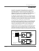
Module Block Diagram 8 FLASH 1 128K X 8 16 SYNC CCLK LOGIC SLOT DECODE CONTROL & ARBITRATION INTERRUPTS (4 OUT,1 IN) MULTIBUS SLAVE INTERFACE (XILINX-FPGA) CPU FLASH 2 See note 1 8 2K X 16 32 20 MHz (0 WAIT-STATE SRAM) MEMORY READ/WRITE CONTROL 16 20 MHz 40 MHz OSC & RESET LOGIC 32-BIT RISC 1KB DATA SRAM 4 DMA CHS. INTERRUPT CNTR.
B-2 Universal Drive Controller Module
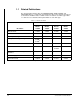
APPENDIX C DPS Hardware and Software Compatibility by Drive Type The Following Hardware and Software Can Be Used . . . Exec. S/W Modules V3.4 V3.5 & Later1 UDC O-575522 UDC EM O-576523 PMIP O-60000 PMIP O-60021 RDI/O O-60001 RDI/O O-60031 SD3000 • • • • • • • • SF3000 • • • • • • • • SA500 • • • • N/A N/A N/A N/A SA3000 • • • • • • • SA3000 Constant Power • • • • • SA3100 • • • • • SB3000 • • • • • • • • For This Drive Type . . .
C-2 Universal Drive Controller Module
DIF Documentation Improvement Form Use this form to give us your comments concerning this publication or to report an error that you have found. For convenience, you may attach copies of the pages with your comments. After you have completed this form, please return it to: Rockwell Automation RGA (Technical Publications) 25001 Tungsten Road Cleveland, Ohio 44117 Fax: 216.266.
Rockwell Automation / 24703 Euclid Avenue / Cleveland, Ohio 44117 / (216) 266-7000 Printed in U.S.A.