Distributed Power System High Power SB3000 AC Power Modules (RCS) 850021 – 21xxx, 31xxx (445 Amp) 850021 – 22xxx, 32xxx (890 Amp) 850021 – 23xxx, 33xxx (1335 Amp) Instruction Manual S-3043
Throughout this manual, the following notes are used to alert you to safety considerations: ! ATTENTION: Identifies information about practices or circumstances that can lead to personal injury or death, property damage, or economic loss. Important: Identifies information that is critical for successful application and understanding of the product.
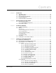
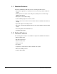
CONTENTS Chapter 1 Introduction 1.1 Standard Features ........................................................................................... 1-2 1.2 Optional Features ............................................................................................ 1-2 1.3 Power Module Part Numbers .......................................................................... 1-3 1.4 Related Publications ........................................................................................ 1-4 1.
Chapter 4 Diagnostics and Troubleshooting (Continued) 4.3.2.5 Reference in Limit Warning .....................................................4-9 4.3.2.6 Load Sharing Warning.............................................................4-9 4.3.2.7 Overtemperature Warning .......................................................4-9 4.3.2.8 Bad Gain Data Warning...........................................................4-9 4.3.2.9 Power Module Overload Warning............................................4-9 4.3.
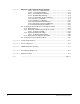
List of Figures Figure 1.1 – SB3000 Power Module Part Numbering Scheme ................................ 1-3 Figure 2.1 – 445A SB3000 Power Module Components .......................................... 2-3 Figure 2.2 – 890A SB3000 Power Module Components .......................................... 2-4 Figure 2.3 – 1335A SB3000 Power Module Components ........................................ 2-5 Figure 2.4 – DC Bus Voltage ....................................................................................
IV SB3000 Power Modules (RCS)
List of Tables Table 1.1 – SB3000 Power Module Configurations.................................................. 1-1 Table 2.1 – Meter Scaling......................................................................................... 2-2 Table 3.1 – Fuse Ratings.......................................................................................... 3-2 Table 3.2 – Pre-charge Resistors and Fuses ........................................................... 3-3 Table 3.3 – Line Filter Reactor Ratings ...........
VI SB3000 Power Modules (RCS)
CHAPTER 1 Introduction The High Power SB3000 Power Modules are variable-voltage, limited-frequency, high performance PWM power converters. They are designed to be used with Distributed Power System (DPS) SA3000 and SA3100 PWM inverter drives and other high performance PWM-type inverters that operate from a fixed voltage DC Bus input.
1.
1.3 Power Module Part Numbers SB3000 Power Module part numbers are organized by the number of cabinet bays, i.e., single (445A), double (890A), or triple (1335A) cabinet bay configurations, in combination with the supplied options. See figure 1.1.
1.4 Related Publications This manual describes the hardware components of the SB3000 Power Module. Refer to the publications listed below for detailed descriptions of the remaining components of the SB3000 system and the configuration and programming necessary to control the SB3000 Power Modules.
CHAPTER 2 Mechanical/Electrical Description This chapter provides an overview the SB3000 Power Module’s main components and their mechanical and electrical characteristics. The SB3000 theory of operation is described in Appendix B. 2.1 Mechanical Description High Power SB3000 Power Modules are housed in protective sheet metal enclosures, as shown in figures 2.1 to 2.3. The Power Modules come in single, double, and triple bay cabinet configurations, depending upon the current rating. See figures 3.1 to 3.
Local Power Interface module (LPI) The LPI module is the interface between the SB3000 Power Module and the PMI rack. It is through this module that information is sent to the SB3000 Power Module and feedback data is sent back to the PMI rack. Capacitor Bank Assembly The capacitor bank's electrolytic capacitors store DC power from the IGBTs.
1. 4. 7. 10. 13. 16. 19. 22. 25. Blower Assembly Pre-charge Assy. Mounting Bracket +/- 15V DC Power Supply LPI Module 25KHz Power Supply Fuse - Critical Power Supplies 115VAC C.B. - Critical Power Power Supply Assembly DC Bus Current Meter 2. 5. 8. 11. 14. 17. 20. 23. 26. IGBT Phase Module Assembly LEM Sensor - DC Bus Output 24V DC Power Supplies 250VA Isolation Transformer Reactor Assembly Fuse - Aux. 115VAC (TB1) Blower Filter Door Interlock Bypass Switch AC Input Current Meter 3. 6. 9. 12. 15. 18.
1. 4. 7. 10. 13. 16. 19. 22. 25. Blower Assembly Pre-charge Assy. Mounting Bracket +/- 15V DC Power Supply LPI Module 25KHz Power Supply Fuse - Critical Power Supplies 115VAC C.B. - Critical Power Power Supply Assembly DC Bus Current Meter 2. 5. 8. 11. 14. 17. 20. 23. 26. IGBT Phase Module Assembly LEM Sensor - DC Bus Output 24V DC Power Supplies 250VA Isolation Transformer Reactor Assembly Fuse - Aux. 115VAC (TB1) Blower Filter Door Interlock Bypass Switch AC Input Current Meter 3. 6. 9. 12. 15. 18.
1. 4. 7. 10. 13. 16. 19. 22. 25. Blower Assembly Pre-charge Assy. Mounting Bracket +/- 15V DC Power Supply LPI Module 25KHz Power Supply Fuse - Critical Power Supplies 115VAC C.B. - Critical Power Power Supply Assembly DC Bus Current Meter 2. 5. 8. 11. 14. 17. 20. 23. 26. IGBT Phase Module Assembly LEM Sensor - DC Bus Output 24V DC Power Supplies 250VA Isolation Transformer Reactor Assembly Fuse - Aux. 115VAC (TB1) Blower Filter Door Interlock Bypass Switch AC Input Current Meter 3. 6. 9. 12. 15. 18.
2.2 Electrical Description AC power to the SB3000 Power Module is supplied from an AC power distribution/ soft-charge cabinet through the AC input reactor. ! ATTENTION: DC bus capacitors retain hazardous voltages after input power has been disconnected. After disconnecting input power, wait ten (10) minutes for the DC bus capacitors to discharge.
When the DC bus operating voltage is reached, the connected inverter power modules may be operated. Note that an SB3000 Power Module cannot support the loading of SA3000/SA3100 Power Modules when the soft-charge resistors are limiting the bus charging current. ! ATTENTION: SA3000/SA3100 Power Modules must be in standby or in regeneration whenever the SB3000 Power Module’ s pre-charge contactor opens. The SB3000 Power Module’s soft-charge resistors may fail if this interlocking restriction is not observed.
Figure 2.
Figure 2.
Figure 2.
Figure 2.
2-12 SB3000 Power Modules (RCS)
CHAPTER 3 Installation Guidelines This chapter provides guidelines and wiring recommendations to be followed when installing SB3000 Power Modules. Hardware installation of the 445A, 890A, and 1335A units is covered. Please refer to the appropriate SA3000/SA3100 instruction manual for information on properly connecting your AC inverter power module to the SB3000 DC bus output. ! 3.1 ATTENTION: The user is responsible for conforming with all applicable local, national, and international codes.
3.2 Wiring ATTENTION: The user is responsible for conforming with all applicable local, national, and international codes. Failure to observe this precaution could result in damage to, or destruction of, the equipment. ! System wiring is to be done according to the supplied wiring diagrams (W/Es), which are application-specific. Sections 3.2.1 through 3.2.6 provide additional information on input fuses, pre-charge components, AC line reactors, and recommended wire types. 3.2.
Table 3.2 – Pre-charge Resistors and Fuses SB3000 Output Rating Resistor P/N Resistance Fuse Rating Fuse P/N 3-Phase Fuse Holder P/N 445 Amp One 3.75Ω Resistor/Phase 402422-3A 15 Amps, 600V RK5 or Equivalent 64676-1BW 49454-21C 890 Amp Two 1.65Ω Resistors/Phase (3.3Ω/Phase) 402422-3C 20 Amps, 600V RK5 or Equivalent 64676-1BX 49454-21C 1,335 Amp Two 1.65 Ω Resistors/Phase (3.
! ATTENTION: The SB3000 Power Module may cause a large variation in the input isolation transformer’s neutral-to-ground voltage in ungrounded and high-resistance grounded systems. This type of high frequency, high level line disturbance may cause improper ground fault detector operation or component failure. Failure to observe this precaution could result in damage to, or destruction of the equipment.
3.2.6 Wire Routing AC input wiring is routed through the top of the cabinet, above AC line terminals 181, 182 and 183. DC output wiring is also routed through the top of the cabinet. DC output wiring is usually connected directly to the DC bus in the overhead enclosure that distributes the DC power to common DC bus SA3000/SA3100 Inverter Power Modules. The AC power distribution cabinet is mounted separately from the SB3000 Power Module but should be positioned conveniently close by.
Figure 3.
Figure 3.
Figure 3.
Figure 3.
3-10 SB3000 Power Modules (RCS)
CHAPTER 4 Diagnostics and Troubleshooting This chapter describes the equipment needed to check the operation of the SB3000 Power Module and the tests to be performed. Included are descriptions of the SB3000 Power Module faults and warnings monitored by the Distributed Power System software. Procedures are also provided for replacing Power Module cabinets, sub-assemblies, and fuses. ! ATTENTION: DC bus capacitors retain hazardous voltages after input power has been disconnected.
! ATTENTION: The Power Module is not isolated from earth ground. AC line powered test instruments used to measure Power Module signals must be isolated from ground through an isolation transformer. This is not necessary for battery-powered test instruments. Failure to observe this precaution could result in bodily injury.
Figure 4.
Table 4.1 – DC Bus and Output Terminal Tests1 Meter Connections + DC Bus Bus Capacitors Input Terminals - Bus (45) + Bus (47) + Bus (47) - Bus (45) + 1249 - 1249 601 + 602 + 603 + + 601 + 602 + 603 181 (601) 182 (602) 181 (601) 183 (603) 182 (602) 183 (603 Scale X10 X10 Expected Test Results Capacitor Effect (0 to 50 ohms) Capacitor Effect (0 to 200 ohms) Capacitor Effect (0 to 500 ohms) X1 2 ohms X10 Capacitor Effect (0 to 2k ohms) X1000 4k to 6k ohms 1.
4.3.1 Faults The following faults will cause the SB3000 Synchronous Rectifier to shut down. See table 4.3. In a fault situation, the PMI Processor will command zero current and will stop firing the Power Modules’ IGBTs; however, the IGBT emitter-collector diodes will supply rectified line voltage to the DC bus until AC input power is disconnected. Faults must be reset before the SB3000 Synchronous Rectifier can be restarted. Table 4.
4.3.1.1 DC Bus Overvoltage Fault The DC Bus Overvoltage bit (bit 0) is set in the Fault register (202/1202) if the DC bus voltage exceeds 900 VDC. Error code 1018 will also be displayed in the error log of the UDC task in which the fault occurred. 4.3.1.2 DC Bus Overcurrent Fault The DC Bus Overcurrent bit (bit 1) is set in the Fault register (202/1202) if the DC bus current exceeds 125% of the rated SB3000 Power Module current.
4.3.1.8 Overtemperature Fault The Overtemperature Fault bit (bit 7) is set in the Fault register (202/1202) if the fault level thermal switch (85o C (185o F)) in the SB3000 Power Module opens. Bit 12 in register 204/1204, 220/1220, or 221/1221 will be set to indicate which SB3000 Power Module is affected. Error code 1016 will also be displayed in the error log of the UDC task in which the fault occurred. 4.3.1.
Table 4.4 – SB3000 Warning Register 203 /1203 Bit Suggested Variable Name Description Summary 0 WRN_OV@ The DC Bus Overvoltage fault bit is set if the DC bus voltage exceeds the overvoltage threshold value stored in local tunable OVT_E0%. 1 WRN_UV@ The DC Bus Under Voltage bit is set if the DC bus voltage drops below the under voltage threshold value stored in local tunable UVT_E0%.
4.3.2.3 Ground Current Warning The Ground Current Warning bit (bit 2) is set in the Warning register (203/1203) if the ground current exceeds the ground fault current level stored in local tunable GIT_EI%. 4.3.2.4 Phase Lost Warning The Phase Lost Warning bit (bit 3) is set in the Warning register (203/1203) if a phase loss occurs in the AC line. 4.3.2.
4.3.2.11 PMI Fan Loss Warning The PMI Fan Loss Warning bit (bit 12) is set in the Warning register (203/1203) if there is no airflow through the PMI rack. 4.3.2.12 Rail Communication Warning The Rail Communication Warning bit (bit 13) is set in the Warning register (203/1203) if a rail communication problem occurs and is logged in registers 4, 10, 16, or 22. 4.3.2.
Table 4.5 – Power Module Replacement Fuse Specifications Fuse Volts Class Type Rating Rockwell Part Number Torque Specifications 1FU 600 CC KLDR 5A 64676-29R -- 3FU 600 CC KLDR 3.2 A 64676-29P -- FPM A,B,C 1000 Semiconductor 1000 A 64676-80P 41 Nm (30 lb-ft) F103 A,B,C 1000 Semiconductor 630 A 64676-79AZ 20.5 Nm (15 lb-ft) F104 A,B,C 1000 Semiconductor 630 A 64676-79AZ 20.5 Nm (15 lb-ft) F105 A,B,C 1000 Semiconductor 630 A 64676-79AZ 20.
(2) (3) (1) (4) (4) Figure 4.
(2) (3) (1) (4) (4) Figure 4.
PRE-CHARGE ASSEMBLY Figure 4.
Figure 4.
Figure 4.6 – 25 KHz.
4.4.2 Replacing an IGBT Phase Module Assembly Important: When replacing an IGBT phase module assembly be sure to re-install, position, and tighten the hardware in the proper sequence. The IGBT phase module must be aligned correctly to prevent damage to the components. If all three IGBT phase modules are to be replaced, it will be easier to remove them by starting at the top and working down, i.e., begin by removing module U, continue with module V, and then finish by removing module W.
Step 11. Start and finger-tighten the two M6 hex nuts on the negative bus bar. See figure 4.7, callout 4. Step 12. Start and finger-tighten the two 5/16” cap screws, flat washers, and lock washers on the heatsink. One cap screw is located on each side of the heatsink. See figure 4.7, callout 5. Step 13. Start and finger-tighten the two M8 bolts on the AC bus bar. See figure 4.7, callout 3. Tighten the bolts evenly. Step 14. Loosen the M8 bolt on the left side of the fuse. See figure 4.7, callout 1.
PHASE V 3 PHASE W 2 5 4 1 Figure 4.7 – IGBT Module Assembly Mounting Bolt Locations 4.4.2.1 Replacing an IGBT If an IGBT needs to be replaced, it is recommended that the IGBT module be returned to an authorized Rockwell repair facility.
4.4.3 Replacing a Blower Assembly Use the following procedure to replace a blower assembly: Step 1. Turn off and lock out the AC input power. Step 2. Wait ten minutes to allow the DC bus voltage to dissipate. ! ATTENTION: DC bus capacitors retain hazardous voltages after input power has been disconnected. After disconnecting input power, wait ten (10) minutes for the DC bus capacitors to discharge.
Step 3. Open the cabinet doors and check the voltage across the DC bus bars, 347 A,B,C (+ bus) and 345 A,B,C (- bus), with an external voltmeter to ensure the DC bus capacitors are discharged before touching any internal components. See figure 4.1. Step 4. Remove all three IGBT assemblies (U, V, and W). Refer to section 4.4.2 for information on IGBT assembly removal. Step 5. Remove the AC input power wiring by removing the bolt from the LEM stud spacer.
Step 4. Disconnect the AC input leads from terminals 181 (L1), 182 (L2), and 183 (L3). Disconnect the GND wire from the ground terminal. See figure 3.4. Step 5. Disconnect the AC input line (two-wire 115 VAC with ground) from the L1 (L), L2 (N), and GND terminals on the control power board. See figure 3.4. Step 6. Disconnect the DC bus from terminals 45 and 47. See figure 3.4. Step 7. Remove the SB3000 Power Module cabinet. Step 8.
APPENDIX A Technical Specifications Ambient Conditions • Operating Temperature: 0 to +40o C (32 to +104o F) • Storage Temperature: -25 to +55o C (-13 to +131o F) • Humidity: 5 to 95%, non-condensing. • Altitude: Do not install above 1000 meters (3300 feet) without derating output current. For every 91.4 meters (300 feet) above 1000 meters (3300 feet), derate the output current by 1%. • Vibration: Sine Wave: 1g., 10-500 Hz., all 3 axes. Shock: 15g., over 6 msec., half sine wave.
• Maximum AC Line Variation: +/- 10% • AC Line Frequency: 25, 50, and 60 Hz, +/- 2 Hz • Frequency Rate of Change: 1Hz/sec • Maximum AC Line Current: 534A, 972A, 1457A • Maximum Phase Imbalance: 5% AC Control Power • AC Input Voltage: 115 VAC • AC Input Frequency: 50/60 Hz DC Output Power • Minimum Output Voltage: 1.414 x VAC x 1.1 x 1.1 • Maximum Output Voltage: 900V • Output Voltage Regulation: +/- 1% • Maximum DC Output Current: (1.
Three-Phase AC Input Voltage • Voltage Range: 200 to 500 Volts, +/- 10% • Frequency Range: 25, 50, and 60 Hz (+/- 2 Hz) • Frequency Rate of Change: 5 Hz/sec • Maximum Phase Imbalance: 5% Output Phase Signals (181-182, 182-183) • Signal Waveform: 10 mA square wave • Phase Accuracy: < 2% • Phase Shift versus Frequency: Phase Shift = 0.
A-4 SB3000 Power Modules (RCS)
APPENDIX B Theory of Operation B.1 Typical SB3000 System SB3000 Power Modules are used to supply regulated common DC bus power to one or more SA3000/SA3100 Power Modules. As illustrated in figure B.
Figure B.
B.2 SB3000 Regulator The main purpose of the SB3000 regulator is to maintain the proper voltage on the DC bus through the use of a vector algorithm executed in the PMI Processor. The application task in the UDC module controlling the SB3000 Power Module passes the desired DC bus voltage reference command to the PMI Processor in register 102/1102. The PMI Processor uses proportional-integral-derivative (PID) logic to calculate DC bus current in response to the voltage reference and error values.
B-4 + + Kp = Vml - Wco C Ki = Vml - Wco Vml - A Filter 25% Kp Ki E1 + z-1 Vml_Kd + – z-1 (Ipf_Ref_E1) (Vdc_Ref_E0) PI_Lmt_E4 PI_Lmt_E1 (Id_Cmd) (Iq_Cmd) Cnf I_Lmt ∗ 1.414 Software Limit Power Factor Current + Min_Vdc_Ref_E0 = Vac_Rms_E0 ∗ 1.414 ∗ 1.1 f(460) = 715 Ramp (Pi_Lmt_E4) (Pi_Lmt_E1) + – 1000 if (!drv_on||restart) Vdc_Ref_E0 = Vdc_Ramp_E1++/10 Vml_Ff Max_Vdc_Ref_E0 = Max_Volts - 25 =875 Filter 40% – + (Vdc_Fbk_E0) (Vdc_Ref_E0) (Idc_Fbk_E1) (Cnf.I_Lmt_E1 ∗ 1.
B.2.1 Leading Power Factor Operation The regulator has the capability to operate with a leading power factor. This allows the regulator to calculate the Id current based on the capacity that is left over in the SB3000 Power Module rating after the Iq current has been determined.
B.3 SB3000 DC Bus Charging Sequence The SB3000 pre-charge circuitry is controlled via a pre-charge contactor which is under the control of the PMI Processor in the SB3000 PMI rack. Any faults relating to pre-charge contactor operation are reported in registers 202/1202 and 205/1205. The closing and opening of the pre-charge contactor is a function of the measured DC bus voltage. See figure B.4.
B.3.3 Pre-charge Contactor’s Close Threshold Voltage When control power is first turned on, the pre-charge contactor will be open. This allows the DC bus voltage to increase to near the peak voltage of the AC line. The pre-charge contactor’s close threshold voltage is equal to the following: Close Threshold Voltage = 1.414 x (Peak Configured AC RMS Line Voltage) - 10% This threshold voltage allows the SB3000 Power Module to turn on when the AC line is up to 10% low.
Control Power On Precharge Is Open Pchg_In == T ( Flt_Chg == F ) && ( ( Vdc > Vdiode ) || ( TST & ( Vdc < 5 ))) Pchg_Out = T Flt_Chg = T Wait To Close Timed Out Flt_Chg = T ( Pchg_In == T ) & ( TST & ( Vdc < 5 )) ( Pchg_In == T) & ( Vdc > Vdiode ) Pchg Is Closed - RUN Pchg_In == F Pchg Is Closed - TST Vdc < PLT Disable Gates Flt_Chg = T Pchg_Out = F Flt_Chg = T Pchg_In == F Flt_Chg = T BRG_TST == F Pchg_Out = F Wait To Open Timed Out Pchg_In == F Flt_Chg = T Figure B.
B.3.5 Pre-charge Contactor Sequencing During the Bridge Test When the bridge test is commanded in register 100/1100, bit 2, the SB3000’s pre-charge contactor will close. After the results of the test have been displayed on the GDI module(s), the pre-charge contactor will be opened. B.3.6 Charge Faults The PMI Processor will generate a Charge Fault (register 202/1202, bit 6) if: • the pre-charge contactor is closed when it should be open. • the pre-charge contactor opens without being commanded to open.
B-10 SB3000 Power Modules (RCS)
APPENDIX C SB3000 Interlock Sequencing When a request is made to turn on the SB3000 Power Module’s voltage loop and a required precondition has not been met, a bit will be set in Interlock register 205/1205 indicating the problem. The interlock requirements are described in the following table. If an interlock problem is detected, the voltage loop will not go into run.
C-2 SB3000 Power Modules (RCS)
APPENDIX D Performing the Bridge Test Important: This test is normally performed at the factory. It should not be necessary to perform it again unless the power devices or fiber-optic cables have been replaced. The bridge test is used to verify fiber-optic gate cabling connections by test firing the IGBTs one at a time. As the IGBTs fire, the LEDs on the corresponding GDI module in the PMI rack will turn on and off in the following sequence: 1. U- (Lower Power Device) 2. U+ (Upper Power Device) 3.
Use the following procedure to perform the bridge test: Step 1. Disconnect, lockout, and tag the three-phase AC input power to the SB3000 Power Module. Step 2. Ensure that the DC bus is fully discharged. Refer to section 4.2 of this manual. Step 3. Enable the bridge test through register 100/1100, bit 2, and bits 10, 11, or 12, as applicable. Step 4. Verify that the LEDs turn on and off in the order described.
APPENDIX E Replacement Parts 445 Amp SB3000 Power Module Table E.
445 Amp SB3000 Power Module (Continued) Table E.3 – Pre-charge Assembly (803430-7R) Quantity Rockwell Part Number Discharge Resistors (8KΩ, 150 W) 9 612183-36R Pre-charge Module 1 0-55350-4 Pre-charge Capacitor (4700uH, 50 VDC) 1 600442-31TS Part Description Table E.4 – Blower Assembly (803430-9R) Quantity Rockwell Part Number Blower (115 VAC) 1 69739-47R Starter Capacitor (40uF, 240 VAC) 1 69932-24QQ Voltage Resistors (10Ω, 90 W) 3 63481-104QAA Part Description Table E.
890 Amp SB3000 Power Module Table E.
890 Amp SB3000 Power Module (Continued) Table E.10 – Blower Assembly (803430-9R) Quantity Rockwell Part Number Blower (115 VAC) 1 69739-47R Starter Capacitor (40uF, 240 VAC) 1 69932-24QQ Voltage Resistors (10Ω, 90 W) 3 63481-104QAA Part Description Table E.
1335 Amp SB3000 Power Module Table E.
1335 Amp SB3000 Power Module (Continued) Table E.16 – Blower Assembly (803430-9R) Quantity Rockwell Part Number Blower (115 VAC) 1 69739-47R Starter Capacitor (40uF, 240 VAC) 1 69932-24QQ Voltage Resistors (10Ω, 90 W) 3 63481-104QAA Part Description Table E.
INDEX A 890A power module circuitry, 2-10 Drive I/O and processor card, 2-8 AC input current meter, 2-2 F B Bridge test, D-1 to D-2 C Cabinet installation, 3-5 to 3-9 double-bay cabinet (890A unit), 3-7 power and ground connections, 3-9 single-bay cabinet (445A unit), 3-6 triple-bay cabinet (1335A unit), 3-8 Cabinet replacement, 4-21 to 4-22 Capacitor bank assembly, 2-2 Components, 2-1 to 2-5 1335A power module, 2-5 445A power module, 2-3 890A power module, 2-4 Configurations, 1-1 Control structure, B-4
wire sizes, 3-4 wiring, 3-2 to 3-5 Interlock sequencing, C-1 Introduction, 1-1 to 1-4 L Leading power factor, B-5 Line filter reactor ratings, 3-3 Local power interface module (LPI), 2-2 M Mechanical description, 2-1 to 2-5 1335A power module components, 2-5 445A power module components, 2-3 890A power module components, 2-4 Mechanical/electrical description, 2-1 to 2-11 Meter scaling, 2-2 Mounting dimensions 1335A triple-bay power module, 3-8 445A single-bay power module, 3-6 890A double-bay power module
load sharing warning, 4-9 overtemperature, 4-9 phase lost, 4-9 PMI communication warning, 4-10 PMI fan loss, 4-10 power loss, 4-9 power module overload, 4-9 Index rail communication warning, 4-10 reference in limit, 4-9 Wiring, 3-2 to 3-5, 3-9 power and ground connections, 3-9 see also Installation guidelines wire routing, 3-5 wire sizes, 3-4 Index-3
Index-4 SB3000 Power Modules (RCS)
DIF Documentation Improvement Form Use this form to give us your comments concerning this publication or to report an error that you have found. For convenience, you may attach copies of the pages with your comments. After you have completed this form, please return it to: Rockwell Automation RGA (Technical Publications) 25001 Tungsten Road Cleveland, Ohio 44117 Fax: 216.266.
Rockwell Automation / 24703 Euclid Avenue / Cleveland, Ohio 44117 / (216) 266-7000 Printed in U.S.A.