
User Manual


Diagnostics and Troubleshooting
4-15
4.5.2 Replacing an IGBT Phase Module Assembly
Use the following procedure to replace an IGBT Phase module assembly (U, V, or W):
Step 1. Turn off and lock out AC input power.
Step 2. Wait ten minutes to allow the DC bus voltage to dissipate.
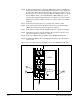
Step 3. Look at the built-in DC Bus Voltage meter. When the DC bus potential is
down to zero volts, open the SB3000 Power Module cabinet's doors and
measure the DC bus potential across the DC bus bars, 1247 A,B,C (+ bus)
and 1145 A,B,C (- bus), with an external voltmeter before working on the unit.
See figure 4.1.
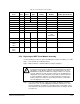
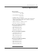
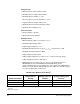
Table 4.5 – Power Module Fuse Specifications
1
Fuse Volts Class Type Rating
Rockwell Part
Number Torque Specifications
1FU 600 CC KLDR 5 A 64676-29R --
2FU 600 CC CCMR 25 A 64676-72BB --
3FU 600 CC KLDR 3.2 A 64676-29P --
F101 1000 Semiconductor 1000 A 64676-80P 41 Nm (30 lb-ft)
F102 1000 Semiconductor 1000 A 64676-80P 41 Nm (30 lb-ft)
F103 1000 Semiconductor 630 A 64676-79AZ 20.5 Nm (15 lb-ft)
F104 1000 Semiconductor 630 A 64676-79AZ 20.5 Nm (15 lb-ft)
F105 1000 Semiconductor 630 A 64676-79AZ 20.5 Nm (15 lb-ft)
+/- 15V PS* 250 -- F 1.8 A Replace with
1.6A
64676-82U
--
+/- 24V PS** 250 -- T 2.5 A 64676-71P --
+/- 24V PS*** 250 -- F 2.0 A 64676-82V --
25 KHz PS
11FU
12FU
600 CC -- 8 A 64676-30H --
25 KHz PS
21FU
26FU
250 -- F 2 A 64676-66C --
1. Fuse locations shown in figures 4.2, 4.3, and 4.4.
!
ATTENTION:
DC bus capacitors retain hazardous voltages after input
power has been disconnected. After disconnecting input power, wait ten
(10) minutes for the DC bus capacitors to discharge, then look at the
built-in DC bus voltage meter. When the voltage is down to zero (0) volts,
open the cabinet doors and check the voltage across the DC bus bars,
1247 A,B,C (+ bus) and 1145 A,B,C (- bus), with an external voltmeter
to ensure the DC bus capacitors are discharged before touching any
internal components. Failure to observe this precaution could result in
severe bodily injury or loss of life.