
User Manual


Power Module Description
2-7
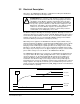
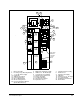
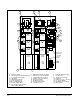
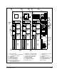
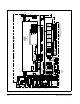
1. Blower Assembly 2. IGBT Phase Module Assembly 3. Capacitor Bank Assembly
4. Pre-charge Assy. Mounting Bracket 5. LEM Sensor - DC Bus Output 6. DC Bus Fuses
7. +/- 15V DC Power Supply 8. 110V AC Disconnect Switch 9. 24V DC Power Supply
10. LPI Module 11. 250VA Isolation Transformer 12. PMI Rack
13. 25KHz Power Supply 14. Reactor Assembly 15. LEM Sensors (3) - AC Input
16. Power Supply Fuses 17. Feedback Resistors 18. Pre-charge Module
19. DC Feedback Module 20. AC Input Current Meter 21. DC Output Current Meter
22. DC Bus Voltage Meter 23. Input Phase Fuses 24. Blower Filter
25. Line Synchronization Module
(On the Meter Bracket)
Figure 2.4 – 1335A SB3000 Power Module Components
CAPACITOR BANK
F102AF102C
F101C F101B
F102B
PWR. MOD. A
F103B
F103C
PHASE U
F105C
F104C
F105B
F104B
POWER MODULE C
AC INPUT
181
182
F103A
LPI CIRCUIT
PHASE U
PMI RACK
PHASE W
BLOWER
F105A
PHASE V
F104A
P1
S
L
O
T
6
S
L
O
T
7
S
L
O
T
8
PWR. MOD. C
PWR. MOD. B
110V
D/S
±15V
PS
F101A
PS
-24V
2FU
3FU
PS
+24V
1FU
2
2
25KHZ PS
8
0
2
2
6
8
-
1
6
R
2
F
U
1
F
U
417114-81A
+
-
2
8
8
2
8
9
24
15
15
15
1
12
2
19
GRD
14
14
15
3
3
GRD
2
6
5
13
CUSTOMER
NAMEPLATE
SALES ORDER
2
0
11
10
7
8
9
(
+
)
(
-
)
4
18
4
18
19
2
2
2
5
CONTROL
WIRING
GDIGDI GDI
14
POWER MODULE B
POWER MODULE A
4
18
183
2
2
2
15
2
2
15
PHASE V
PHASE W
PHASE U
PHASE V
PHASE W
15
15
3
24
24
CAPACITOR BANK
CAPACITOR BANK
15
23
23
23
1
6
ASSEMBLY
BLOWER
1
ASSEMBLY
BLOWER
1
ASSEMBLY
2
1