Distributed Power System High Power SB3000 AC Power Modules (Rittal) 804300-S (445 Amp) 804300-T (890 Amp) 804300-V (1335 Amp) Instruction Manual S-3031
Throughout this manual, the following notes are used to alert you to safety considerations: ! ATTENTION: Identifies information about practices or circumstances that can lead to personal injury or death, property damage, or economic loss. Important: Identifies information that is critical for successful application and understanding of the product.
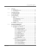
CONTENTS Chapter 1 Introduction 1.1 Standard Features ........................................................................................... 1-2 1.2 Power Module Part Numbers .......................................................................... 1-2 1.3 Related Publications ........................................................................................ 1-3 Chapter 2 Power Module Description 2.1 Mechanical Description ......................................................................
Chapter 4 Diagnostics and Troubleshooting (Continued) 4.3.2.8 Bad Gain Data Warning...........................................................4-9 4.3.2.9 Power Module Overload Warning............................................4-9 4.3.2.10 Power Loss Warning ...............................................................4-9 4.3.2.11 PMI Fan Loss Warning ..........................................................4-10 4.3.2.12 Rail Communication Warning ................................................4-10 4.
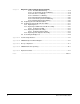
List of Figures Figure 2.1 – DC Bus Voltage .................................................................................... 2-3 Figure 2.2 – 445A SB3000 Power Module Components .......................................... 2-5 Figure 2.3 – 890A SB3000 Power Module Components .......................................... 2-6 Figure 2.4 – 1335A SB3000 Power Module Components ........................................ 2-7 Figure 2.5 – 445A SB3000 Power Module Circuitry ............................................
IV SB3000 Power Modules (Rittal)
List of Tables Table 1.1 – SB3000 Power Module Current Ratings................................................ 1-1 Table 1.2 – SB3000 Part Numbers........................................................................... 1-2 Table 2.1 – Meter Scaling......................................................................................... 2-2 Table 3.1 – AC Input and DC Bus Fuse Ratings ...................................................... 3-2 Table 3.2 – Pre-charge Resistors and Fuses ....................
VI SB3000 Power Modules (Rittal)
CHAPTER 1 Introduction The High Power SB3000 Power Modules are variable-voltage, limited-frequency, high performance PWM power converters. They are designed to be used with Distributed Power System (DPS) SA3000 and SA3100 PWM inverter drives and other high performance PWM-type inverters that operate from a fixed voltage DC Bus input.
1.
1.3 Related Publications This manual describes the hardware components of the SB3000 Power Module. Refer to the publications listed below for detailed descriptions of the remaining components of the SB3000 system and the configuration and programming necessary to control the SB3000 Synchronous Rectifier.
1-4 SB3000 Power Modules (Rittal)
CHAPTER 2 Power Module Description This chapter provides an overview the Power Module’s main components and their mechanical and electrical characteristics. Refer to Appendix B for a block diagram of the Power Module. The SB3000 theory of operation is described in Appendix C. 2.1 Mechanical Description High Power SB3000 Power Modules are housed in protective sheet metal enclosures, as shown in figures 2.2 to 2.4.
Capacitor Bank Assembly The capacitor bank's electrolytic capacitors store DC power from the IGBTs. DC Bus Voltage Meter The DC Bus Voltage meter, which is connected directly across the DC bus, measures the DC bus voltage being supplied by the SB3000 Power Module. AC Input Current Meter and DC Bus Current Meter The AC Input Current and DC Bus Current meters measure the AC input current being provided to the Power Module and the DC bus output current supplied by the SB3000 Power Module.
2.2 Electrical Description AC power to the SB3000 Power Module is supplied from an AC power distribution/ soft-charge cabinet through the AC input reactor. ! ATTENTION: DC bus capacitors retain hazardous voltages after input power has been disconnected. After disconnecting input power, wait ten (10) minutes for the DC bus capacitors to discharge, then look at the built-in DC bus voltage meter.
When the DC bus operating voltage is reached, the connected SA3000/SA3100 Power Modules may be operated. Note that an SB3000 Power Module cannot support the loading of SA3000/SA3100 Power Modules when the soft-charge resistors are limiting the bus charging current. ! ATTENTION: SA3000/SA3100 Power Modules must be in standby or in regeneration whenever the SB3000 Power Module’ s pre-charge contactor opens.
22 5 POWER MODULE A AC INPUT 6 GRD 181 182 183 GRD F102A F101A 7 14 8 9 17 110V D/S 4 ±15V PS 18 19 16 1FU 2FU 3FU 2 15 -24V PS +24V PS 21 LPI CIRCUIT F103A 20 PHASE U 10 CAPACITOR BANK 3 11 2 F105A PWR. MOD. B PWR. MOD. C SLOT 8 PMI RACK 2 15 25 GDI GDI GDI P1 PWR. MOD. A PHASE V SLOT 6 15 F104A SLOT 7 23 PHASE W 12 SALES ORDER NAMEPLATE CUSTOMER CONTROL WIRING BLOWER ASSEMBLY 25KHZ PS 417114-81A 289 + - 288 13 1 2FU 1FU 24 802268-16R 1. 4. 7. 10. 13.
14 6 14 POWER MODULE B 5 POWER MODULE A AC INPUT GRD 181 183 182 GRD F102B F101B F102A F101A 7 17 8 (+) 22 4 ±15V PS 18 18 15 9 110V D/S 4 2 15 19 -24V PS +24V PS 16 1FU 2FU 3FU 2 21 LPI CIRCUIT PHASE U 3 PHASE W F105A PMI RACK PWR. MOD. A P1 2 PWR. MOD. B 15 25 GDI GDI GDI PWR. MOD.
14 14 5 14 6 POWER MODULE A POWER MODULE B POWER MODULE C AC INPUT GRD 181 182 183 GRD F102C F101C F102B F101B F102A F101A 19 (-) 7 (+) 8 22 4 18 15 4 18 2 15 2 4 18 ±15V PS -24V PS +24V PS 16 1FU 2FU 3FU 2 15 19 9 110V D/S 21 LPI CIRCUIT PHASE U 2 23 PHASE V F104C 15 F105C 15 2 23 PHASE V F104B 15 PHASE W 2 2 P1 PMI RACK 2 15 F105A 25 GDI GDI GDI PHASE V F104A PHASE W F105B 2 15 PHASE W PWR. MOD. B 15 11 PWR. MOD. A 23 3 PWR. MOD.
BLK ORG 1 P4 P2 O-60044 145 147 GRN X2 / 2 1 2FU 25A 1FU 6A X1 BRN WHT/BRN BRN WHT BRN WHT BRN WHT BRN WHT/BRN BRN WHT/BRN (612183-14RR) / 4 CON4 BLK +15V 0V 0V -15V L1 N ±15V PS WHT GRN BLU BLK RED / 2 / 2 / 6 WHT BRN 1 / 2 6 WHT CN104 CN105 / 6 RED A2 WHT RED BLK BLU GRN WHT BRN 1 / 4 / TT 24V 24V 0V 0V L1 N 1 +M - +M - +M - (612183-22R) LEM W LEM V LEM U CON2 CN102 1 1 COM 2 + COM 3 + COM 4 COM WHT YEL ORG DC BUS CURRENT + 12
GRAY BAND 4 1 RED/GRY BRN 110VAC QUICK CONNECT BLOCK WHT BLK CN101 (612183-14RR) (612183-21R) 3 1 CN101 B/M-60027 PWR.
281 282 283 L N (612183-29R) BLK ORG 1 X2 1FU 6A X1 P2 GRN BRN WHT/BRN BRN WHT BRN WHT BRN WHT BRN WHT/BRN BRN WHT/BRN RED / 2 (803430-95RX) 1000A F102A GRAY 1000A F101A / 4 CON4 BLK +15V 0V 0V -15V L1 N ±15V PS WHT GRN BLU BLK RED WHT BRN 1 / WHT/BRN 6 WHT (612183-19R) CN104 / 6 RED A2 DOOR SOLENOID 24V 24V 0V 0V L1 N WHT RED BLK BLU GRN WHT BRN / TT 24V 24V 0V 0V L1 N 1 CLR 1 / 9 1 LEM W +M - LEM V +M - LEM U +M - DRAIN WIRE GND AT MTG SCR
GRAY BAND 3 WHT/BRN 110VAC QUICK CONNECT BLOCK B/M-60027 PWR.MOD A CON1 WHT BLK CN101 (612183-14RR) (612183-21R) (612183-19R) 1 BRN 3 CN101 PRE-CHARGE BOARD CN101 PWR.
110VAC QUICK CONNECT BLOCK WHT BLK CN101 (612183-14RS) (612183-21S) 3 1 3 1 4 1 CN101 B/M-60027 PWR.
281 282 283 BUS L N (612183-29R) BLK ORG 1 3 X1 H2 H1 X2 P2 GRN CN106 (O-55350-15) W PHASE P/M A / 2 / 2 BRN WHT/BRN BRN WHT/BRN BRN WHT/BRN BRN WHT BRN WHT BRN WHT 1000A F102A / 2 / 4 / 2 CON4 BLK +15V 0V 0V -15V L1 N ±15V PS WHT BLU BLK RED GRN WHT BRN 1 WHT/BRN 6 WHT BRN CN104 CN105 24V 24V 0V 0V L1 N / 6 RED (612183-11R) A2 WHT RED BLK BLU GRN WHT BRN TT 24V 24V 0V 0V L1 N 1 / 9 1 (612183-28S) 4 / LEM V +M - LEM U +M - +M - +M - +M -
4 1 RED/GRY BRN 3 110VAC QUICK CONNECT BLOCK B/M-60027 PWR.MOD A CON1 WHT BLK CN101 (612183-14RR) (612183-21R) (612183-19R) 1 BRN WHT/BRN CN101 PRE-CHARGE BOARD CN101 PWR.
GRAY BAND 110VAC QUICK CONNECT BLOCK WHT BLK CN101 (612183-14RT) (612183-21T) 3 1 3 1 4 1 5 9 CN104 GRD (FRAME) GRD 6 U2 TK GRD CONNECTOR 3 4 3 4 1 2 1 1 CON1 BLOWER 4 2 3 + C12 2 3 2 1 (612183-9S) O-55350-4 5 RED/GRY 7 6 CLR 4 CLR 2 BLK 1 BLK U2 BLK WHT RED - M + GRD Z2 U2 TK TERMINAL BLOCK GRD Z2 U2 TK BLOWER ASSEMBLY Z2 U2 (612183-15RR) 10 OHMS 10 OHMS 10 OHMS <1 (612183-32RR) ORG BAND 1601 LEM U IGBT MODULE [U] FAULT THERM.
110VAC QUICK CONNECT BLOCK WHT BLK CN101 (612183-14RS) (612183-21R) 3 1 3 1 4 1 CN101 B/M-60027 PWR.
CHAPTER 3 Installation Guidelines This chapter describes the guidelines and wiring recommendations to be followed when installing High Power SB3000 Power Modules. An installation procedure for the 445A, 890A, and 1335A Power Modules is provided. ! 3.1 ATTENTION: The user is responsible for conforming with all applicable local, national, and international codes. Failure to observe this precaution could result in damage to, or destruction of, the equipment.
3.2 Wiring ATTENTION: The user is responsible for conforming with all applicable local, national, and international codes. Failure to observe this precaution could result in damage to, or destruction of, the equipment. ! System wiring is to be done according to the supplied wiring diagrams (W/Es), which are application-specific. Sections 3.2.1 through 3.2.6 provide additional information on input fuses, pre-charge components, AC line reactors, and recommended wire types. 3.2.
Table 3.2 – Pre-charge Resistors and Fuses Power Module Rating Resistor P/N Resistance Fuse Rating Fuse P/N 3-Phase Fuse Holder P/N 445 Amp One 3.75Ω Resistor/Phase 402422-3A 15 Amps, 600V RK5 or Equivalent 64676-1BW 49454-21C 890 Amp Two 1.65Ω Resistors/Phase (3.3Ω/Phase) 402422-3C 20 Amps, 600V RK5 or Equivalent 64676-1BX 49454-21C 1,335 Amp Two 1.65 Ω Resistors/Phase (3.
! ATTENTION: The SB3000 Power Module may cause a large variation in the input isolation transformer’s neutral-to-ground voltage in ungrounded and high-resistance grounded systems. This type of high frequency, high level line disturbance may cause improper ground fault detector operation or component failure.Failure to observe this precaution could result in damage to, or destruction of the equipment.
3.2.6 Wire Routing AC input wiring is routed through the top of the cabinet, above AC line terminals 181, 182 and 183. DC output wiring is also routed through the top of the cabinet. DC output wiring is usually connected directly to the D-C bus in the overhead enclosure that distributes the DC power to the common DC bus SA3000/SA3100 Power Modules. The AC power distribution cabinet is mounted separately from the SB3000 Power Module but should be positioned conveniently close by.
4.00 (101.6) 1.75 (44.5) 10.50 (266.8) 8.00 (203.3) 1.34 (34.03) 1.00 (25.5) 1.75 (44.5) 1.00 (25.4) 1.125 (28.6) TOP VIEW .562 X .750 (4) PL. 4.56 (115.8) 2 (50.8) 5.31 (134.4) 2.69 (68.2) 10.50 (266.7) 5.25 (133.4) .24 (6.00) 15.75 (400.26) GRD (-) BUS (45) 181 182 183 C L AC INPUT 181 182 183 GRD 14.67 (372.5) AC INPUT 10.31 (261.9) SEE DETAIL "A" FOR DIMENSIONS OF STAB. (+) BUS (47) 2.63 (66.68) C L 26.25 (667) 7.13 (180.98) FRONT VIEW 18.87 (479.2) 4.75 (120.
TOP VIEW 63.50 (1612.0) 1.00 (25.5) AC INPUT 14.66 (372.5) 10.50 (266.8) 8.00 (203.3) 1.34 (66.7) 1.34 (34.03) 18.84 (478.7) (+) BUS (47) (-) BUS (45) 181 182 183 4.56 (115.8) 2.69 (68.2) 10.31 (261.9) 2 (50.8) 48.14 (1222.8) 21.69 (550.9) 4.00 (101.6) 1.75 (44.5) 1.125 (28.6) 4.75 (120.5) 6.00 (152.4) C L C L 7.13 (181.0) 9.50 (241.3) 4.75 (120.7) FRONT VIEW DETAIL "A" 1.00 (25.4) 1.75 (44.5) .562 x .750 (4) PL. SEE DETAIL "A" FOR DIMENSIONS OF STAB. 15.64 (397.
87.09 (2212.0) 1.00 (25.5) TOP VIEW 14.66 (372.5) 10.50 (266.8) AC INPUT 8.00 (203.3) 18.84 (478.7) 2.63 (66.7) 1.34 (34.03) (+) BUS (47) (-) BUS (45) 181 182 183 4.56 (115.8) 2.69 (68.2) 4.75 (120.5) C L FRONT VIEW .562 x .750 (4) PL. 6.00 (152.4) C L 1.75 (44.5) 10.31 (261.9) 1.00 (25.4) 7.13 (181.0) 9.50 (241.3) 1.125 (28.6) 4.75 (120.7) 4.00 (101.6) 1.75 (44.5) 2 (50.8) 48.14 (1222.8) 21.69 (550.9) DETAIL "A" SEE DETAIL "A" FOR DIMENSIONS OF STAB. 15.64 (397.
THREE PHASE AC INPUT FROM LINE REACTOR GND 181 182 115 VAC INPUT VOLTAGE L 183 N 115 VAC QUICK CONNECT BLOCK – + SB3000 POWER MODULE FUSE GND 45 (–) 47 (+) DC BUS OUTPUT VOLTAGE Figure 3.
3-10 SB3000 Power Modules (Rittal)
CHAPTER 4 Diagnostics and Troubleshooting This chapter describes the equipment needed to check the operation of the SB3000 Power Module and the tests to be performed. Also included are descriptions of the SB3000 Power Module faults monitored by the Distributed Power System software. Procedures are provided for replacing fuses and sub-assemblies. ! ATTENTION: DC bus capacitors retain hazardous voltages after input power has been disconnected.
! ATTENTION: The Power Module is not isolated from earth ground. The test instruments used to measure Power Module signals must be isolated from ground through an isolation transformer. This is not necessary for battery-powered test instruments. Failure to observe this precaution could result in bodily injury.
POWER MODULE A AC MOTOR OUTPUT MOTOR GRD U V W GRD F102A F101A 110V D/S ±15V PS -24V PS +24V PS 1FU 2FU 3FU CAPACITOR BANK LPI CIRCUIT F103A PHASE U PWR. MOD. B PWR. MOD. C SLOT 8 PHASE W PWR. MOD. A F105A PMI RACK SLOT 6 PHASE V SLOT 7 GDI GDI GDI F104A DC BUS VOLTAGE MEASURING POINTS 1247A +BUS 25KHZ PS 289 + - 288 2FU 1FU 1145A -BUS FAN ASSEMBLY Figure 4.
Table 4.1 – DC Bus and Output Terminal Tests1 Meter Connections + DC Bus Bus Capacitors Input Terminals - Bus (45) + Bus (47) + Bus (47) - Bus (45) + 1249 - 1249 601 + 602 + 603 + + 601 + 602 + 603 181 (601) 182 (602) 181 (601) 183 (603) 182 (602) 183 (603 Scale X10 X10 Expected Test Results Capacitor Effect (0 to 50 ohms) Capacitor Effect (0 to 200 ohms) Capacitor Effect (0 to 500 ohms) X1 2 ohms X10 Capacitor Effect (0 to 2k ohms) X1000 4k to 6k ohms 1.
4.3.1 Faults The following faults will cause the SB3000 Power Module to shut down. See table 4.3. In a fault situation, the PMI Processor will command zero current and will stop firing the IGBTs; however, the IGBT emitter-collector diodes will supply rectified line voltage to the DC bus until AC input power is disconnected. Faults must be reset before the SB3000 Power Module can be restarted. Table 4.
4.3.1.1 DC Bus Overvoltage Fault The DC Bus Overvoltage bit (bit 0) is set in the Fault register (202/1202) if the DC bus voltage exceeds 900 VDC. Error code 1018 will also be displayed in the error log of the UDC task in which the fault occurred. 4.3.1.2 DC Bus Overcurrent Fault The DC Bus Overcurrent bit (bit 1) is set in the Fault register (202/1202) if the DC bus current exceeds 125% of the rated SB3000 Power Module current.
4.3.1.8 Overtemperature Fault The Overtemperature Fault bit (bit 7) is set in the Fault register (202/1202) if the fault level thermal switch (85o C (185o F)) in the SB3000 Power Module opens. Bit 12 in register 204/1204, 220/1220, or 221/1221 will be set to indicate which SB3000 Power Module is affected. Error code 1016 will also be displayed in the error log of the UDC task in which the fault occurred. 4.3.1.
Table 4.4 – SB3000 Warning Register 203 /1203 Bit Suggested Variable Name Description Summary 0 WRN_OV@ The DC Bus Overvoltage fault bit is set if the DC bus voltage exceeds the overvoltage threshold value stored in local tunable OVT_E0%. 1 WRN_UV@ The DC Bus Under Voltage bit is set if the DC bus voltage drops below the under voltage threshold value stored in local tunable UVT_E0%.
4.3.2.3 Ground Current Warning The Ground Current Warning bit (bit 2) is set in the Warning register (203/1203) if the ground current exceeds the ground fault current level stored in local tunable GIT_EI%. 4.3.2.4 Phase Lost Warning The Phase Lost Warning bit (bit 3) is set in the Warning register (203/1203) if a phase loss occurs in the AC line. 4.3.2.
4.3.2.11 PMI Fan Loss Warning The PMI Fan Loss Warning bit (bit 12) is set in the Warning register (203/1203) if there is no airflow through the PMI rack. 4.3.2.12 Rail Communication Warning The Rail Communication Warning bit (bit 13) is set in the Warning register (203/1203) if a rail communication problem occurs and is logged in registers 4, 10, 16, or 22. 4.3.2.
Step 8. Install the replacement SB3000 Power Module cabinet by following these steps in reverse order. 4.5 Replacing Power Module Sub-Assemblies Use the procedures in sections 4.5.1 to 4.5.4 to replace the SB3000 Power Module’s fuses and sub-assemblies. 4.5.1 Replacing Fuses Use the following procedure to replace a fuse that has blown: Step 1. Turn off and lock out the AC input power. Step 2. Wait ten minutes to allow the DC bus voltage to dissipate.
AC INPUT 181 182 183 F102A F101A DC Bus Fuses POWER MODULE A ∗ 110V. D/S ±15V PS Control Power Fuses CAPACITOR BANK F103A PHASE U –24V PS +24V PS ∗∗ See Table 4.5 ∗∗∗ 1FU 2FU 3FU LPI CIRCUIT F104A PHASE V PMI RACK 11FU 12FU F105A PHASE W SLOT 6 AC Input Phase Fuses PWR. MOD. A GDI 25KHZ. PS 21FU26FU Figure 4.
AC INPUT 181 182 183 F102B F101B DC Bus Fuses F102A F101A (+) POWER MODULE B POWER MODULE A ∗∗∗ See Table 4.5 ∗ ∗∗ 110V D/S +- ±15V PS Control Power Fuses LPI CIRCUIT AC Input Phase Fuses PHASE V F104A GDI GDI PHASE V PMI RACK 11FU 12FU F105B PHASE W F105A PHASE W 25KHZ PS PWR. MOD B F104B PHASE U PWR. MOD A AC Input Phase Fuses F103A 1FU 2FU 3FU SLOT 7 PHASE U -24V PS SLOT 6 F103B +24V PS 21FU26FU Figure 4.
Figure 4.4 – 1335A SB3000 Power Module Fuse Locations F105C F104C AC Input Phase Fuses PHASE W PHASE V F105B F104B AC Input Phase Fuses PHASE W PHASE V PHASE U F103B PHASE U F103C POWER MODULE B POWER MODULE C 181 182 183 AC INPUT F105A F104A AC Input Phase Fuses F103A PHASE W PHASE V PHASE U POWER MODULE A F102C F101C F102B F101B F102A F101A DC Bus Fuses 11FU 12FU 1FU 2FU 3FU +24V PS 25KHZ.
Table 4.5 – Power Module Fuse Specifications1 Fuse Volts Class Type Rating Rockwell Part Number Torque Specifications 1FU 600 CC KLDR 5A 64676-29R -- 2FU 600 CC CCMR 25 A 64676-72BB -- 3FU 600 CC KLDR 3.2 A 64676-29P -- F101 1000 Semiconductor 1000 A 64676-80P 41 Nm (30 lb-ft) F102 1000 Semiconductor 1000 A 64676-80P 41 Nm (30 lb-ft) F103 1000 Semiconductor 630 A 64676-79AZ 20.5 Nm (15 lb-ft) F104 1000 Semiconductor 630 A 64676-79AZ 20.
Step 4. Remove the wiring harnesses from the IGBT Phase module assembly. The wiring includes the power supply wiring, the temperature sensor wiring, and the fiber-optic cables. Remove the fiber-optic cables by pressing the sides of the connectors to release the locking mechanism. Label the harnesses to aid in re-installation. Refer to the wiring diagrams supplied with your system.
4.5.2.1 Replacing an IGBT If an IGBT needs to be replaced, it is recommended that the IGBT module be returned to an authorized Rockwell repair facility. 4.5.3 Replacing a Blower Assembly Use the following procedure to replace a blower assembly: Step 1. Turn off and lock out the AC input power. Step 2. Wait ten minutes to allow the DC bus voltage to dissipate. ! ATTENTION: DC bus capacitors retain hazardous voltages after input power has been disconnected.
4.5.4 Replacing a Bus Capacitor Assembly Use the following procedure to replace a DC bus capacitor assembly: Step 1. Turn off and lock out the AC input power. Step 2. Wait ten minutes to allow the DC bus voltage to dissipate. ! ATTENTION: DC bus capacitors retain hazardous voltages after input power has been disconnected. After disconnecting input power, wait ten (10) minutes for the DC bus capacitors to discharge, then look at the built-in DC bus voltage meter.
4.6 Performing the Bridge Test Important: This test is normally performed at the factory. It should not be necessary to perform it again unless the power devices or fiber-optic cables have been replaced. The bridge test is used to verify fiber-optic gate cabling connections by test firing the IGBTs one at a time. As the IGBTs fire, the LEDs on the corresponding GDI module in the PMI rack will turn on and off in the following sequence: 1. U- (Lower Power Device) 2. U+ (Upper Power Device) 3.
4-20 SB3000 Power Modules (Rittal)
APPENDIX A Technical Specifications Ambient Conditions • Operating Temperature:0 to +40o C 32 to +104o F • Storage Temperature:-25 to +55o C -13 to +131o F • Humidity: 5 to 95%, non-condensing. • Altitude: Do not install above 1000 meters (3300 feet) without derating output current. For every 91.4 meters (300 feet) above 1000 meters (3300 feet), derate the output current by 1%. • Vibration: Sine Wave: 1g., 10-500 Hz., all 3 axes. • Shock: 15g., over 6 msec., half sine wave.
AC Input Power • Minimum AC Line Voltage: 208V nominal • Maximum AC Line Voltage: 460V nominal • Maximum AC Line Variation: +/- 10% • AC Line Frequency: 25, 50, and 60 Hz, +/- 2 Hz • Frequency Rate of Change: 1Hz/Second • Maximum AC Line Current: 534A, 972A, 1457A • Maximum Phase Imbalance: 5% AC Control Power • AC Input Voltage: 115 VAC • AC Input Frequency: 50/60 Hz DC Output Power • Minimum Output Voltage: 1.414 x VAC x 1.1 x 1.
TSB3000 Power Module Replacement Fuse Specifications 1 Fuse Volts Class Type Rating Rockwell Part Number Torque Specifications 1FU 600 CC KLDR 5A 64676-29R -- 2FU 600 CC CCMR 25 A 64676-72BB -- 3FU 600 CC KLDR 3.2 A 64676-29P -- F101 1000 Semiconductor 1000 A 64676-80P 41 Nm (30 lb-ft) F102 1000 Semiconductor 1000 A 64676-80P 41 Nm (30 lb-ft) F103 1000 Semiconductor 630 A 64676-79AZ 20.5 Nm (15 lb-ft) F104 1000 Semiconductor 630 A 64676-79AZ 20.
A-4 SB3000 Power Modules (Rittal)
APPENDIX B SB3000 Component Block Diagram The following figure shows an overview of the components of the SB3000 Synchronous Rectifier. Refer to chapter 2 of this manual for detailed diagrams of the 445A, 890A, and 1335A configurations of the SB3000 Synchronous Rectifier.
B-2 SB3000 Power Modules (Rittal) + - G G N L DC BUS 188 189 89 115VAC CKT BREAKER LEM 88 45 47 LINE SYNC 1000A F102A 1000A F101A 1000A F102B 1000A F101B 1000A F101C 1000A F102C 1145 1147 2145 2147 3145 3147 189 188 189 188 DC BUS_3 DC BUS_2 +24 VDC -24 VDC +/-15 VDC 1388 1189 1388 1189 1388 1188 189 115VAC DC BUS_1 188 - + 115VAC - + 115VAC - + 2 TO PRE-CHARGE IN PWR. DISC.
APPENDIX C Theory of Operation C.1 Typical SB3000 System SB3000 Power Modules are used to supply regulated common DC bus power to one or more SA3000/SA3100 Power Modules. As illustrated in figure C.
Figure C.
C.2 SB3000 Regulator The main purpose of the SB3000 regulator is to maintain the proper voltage on the DC bus through the use of a vector algorithm executed in the PMI Processor. The application task in the UDC module controlling the SB3000 Power Module passes the desired DC bus voltage reference command to the PMI Processor in register 102/1102. The PMI Processor uses proportional-integral-derivative (PID) logic to calculate DC bus current in response to the voltage reference and error values.
C-4 + + Kp = Vml - Wco C Ki = Vml - Wco Vml - A Filter 25% Ki E1 + z-1 Vml_Kd Kp z-1 (Ipf_Ref_E1) (Vdc_Ref_E0) PI_Lmt_E4 (Id_Cmd) (Iq_Cmd) Cnf I_Lmt ∗ 1.414 Software Limit Power Factor Current + – – PI_Lmt_E1 + Min_Vdc_Ref_E0 = Vac_Rms_E0 ∗ 1.414 ∗ 1.1 f(460) = 715 Ramp (Pi_Lmt_E4) (Pi_Lmt_E1) + (Vdc_Fbk_E0) 1000 if (!drv_on||restart) Vdc_Ref_E0 = Vdc_Ramp_E1++/10 Vml_Ff Max_Vdc_Ref_E0 = Max_Volts - 25 =875 Filter 40% – + (Vdc_Ref_E0) (Idc_Fbk_E1) (Cnf.I_Lmt_E1 ∗ 1.
C.2.1 Leading Power Factor Operation The regulator has the capability to operate with a leading power factor. This allows the regulator to calculate the Id current based on the capacity that is left over in the SB3000 Power Module rating after the Iq current has been determined.
C.3 SB3000 DC Bus Charging Sequence The SB3000 pre-charge circuitry is controlled via a pre-charge contactor which is under the control of the PMI Processor in the SB3000 PMI rack. Any faults relating to pre-charge contactor operation are reported in registers 202/1202 and 205/1205. The closing and opening of the pre-charge contactor is a function of the measured DC bus voltage. See figure C.4.
C.3.3 Pre-charge Contactor’s Close Threshold Voltage When control power is first turned on, the pre-charge contactor will be open. This allows the DC bus voltage to increase to near the peak voltage of the AC line. The pre-charge contactor’s close threshold voltage is equal to the following: Close Threshold Voltage = 1.414 x (Peak Configured AC RMS Line Voltage) - 10% This threshold voltage allows the SB3000 Power Module to turn on when the AC line is up to 10% low.
&RQWURO 3RZHU 2Q 3UHFKDUJH ,V 2SHQ 3FKJB,Q 7 )OWB&KJ 7 )OWB&KJ ) 9GF ! 9GLRGH __ 767 9GF 3FKJB2XW 7 :DLW 7R &ORVH 7LPHG 2XW )OWB&KJ 7 3FKJB,Q 7 767 9GF 3FKJB,Q 7 9GF ! 9GLRGH 3FKJ ,V &ORVHG 581 3FKJB,Q ) )OWB&KJ 7 3FKJ ,V &ORVHG 767 9GF 3/7 'LVDEOH *DWHV )OWB&KJ 7 3FKJB2XW ) 3FKJB,Q ) )OWB&KJ 7 %5*B767 ) 3FKJB2XW ) :DLW 7R 2SHQ 7LPHG 2XW )OWB&KJ 7 3FKJB,Q ) Figure C.
C.3.5 Pre-charge Contactor Sequencing During the Bridge Test When the bridge test is commanded in register 100/1100, bit 2, the SB3000’s pre-charge contactor will close. After the results of the test have been displayed on the GDI module(s), the pre-charge contactor will be opened. C.3.6 Charge Faults The PMI Processor will generate a Charge Fault (register 202/1202, bit 6) if: • the pre-charge contactor is closed when it should be open. • the pre-charge contactor opens without being commanded to open.
C-10 SB3000 Power Modules (Rittal)
APPENDIX D SB3000 Interlock Sequencing When a request is made to turn on the SB3000 Power Module’s voltage loop and a required precondition has not been met, a bit will be set in Interlock register 205/1205 indicating the problem. The interlock requirements are described in the following table. If an interlock problem is detected, the voltage loop will not go into run.
D-2 SB3000 Power Modules (Rittal)
APPENDIX E Replacement Parts 445 Amp SB3000 Synchronous Rectifier Table E.
445 Amp SB3000 Synchronous Rectifier (Continued) Table E.3 – Pre-charge Assembly (803430-7R) Quantity Rockwell Part Number 9 612183-36R Pre-charge Module 1 0-55350-4 Pre-charge Capacitor (4700uH, 50 VDC) 1 600442-31TS Part Description 'LVFKDUJH 5HVLVWRUV .Ω : Table E.4 – Blower Assembly (803430-9R) Quantity Rockwell Part Number Blower (115 VAC) 1 69739-47R Starter Capacitor (40uF, 240 VAC) 1 69932-24QQ 3 63481-104QAA Part Description 9ROWDJH 5HVLVWRUV Ω : Table E.
890 Amp SB3000 Synchronous Rectifier Table E.
890 Amp SB3000 Synchronous Rectifier (Continued) Table E.10 – Blower Assembly (803430-9R) (2 Required) Quantity Rockwell Part Number Blower (115 VAC) 1 69739-47R Starter Capacitor (40uF, 240 VAC) 1 69932-24QQ 3 63481-104QAA Part Description 9ROWDJH 5HVLVWRUV Ω : Table E.
1335 Amp SB3000 Synchronous Rectifier Table E.
1335 Amp SB3000 Synchronous Rectifier (Continued) Table E.16 – Blower Assembly (803430-9R) (3 Required) Quantity Rockwell Part Number Blower (115 VAC) 1 69739-47R Starter Capacitor (40uF, 240 VAC) 1 69932-24QQ 3 63481-104QAA Part Description 9ROWDJH 5HVLVWRUV Ω : Table E.
INDEX B Bridge test see Diagnostics and troubleshooting C Control structure, C-4 Current ratings, 1-1 D DC bus voltage, 2-3 Diagnostics and troubleshooting, 4-1 to 4-19 bridge test, 4-19 DC bus and output terminal tests, 4-4 faults and warnings, 4-4 to 4-10 IGBT tests, 4-4 replacing a blower assembly, 4-17 replacing a blower filter, 4-17 replacing a bus capacitor assembly, 4-18 replacing an IGBT phase module, 4-15 to 4-17 replacing fuses, 4-11 to 4-15 replacing sub-assemblies, 4-11 to 4-18 replacing the c
phase modules, 2-1 snubber/gate driver module, 2-1 softcharge assembly, 2-2 Mechanical/electrical description, 2-1 to 2-16 Meter scaling, 2-2 Meters, 2-2 Mounting dimensions 1335A power module, 3-8 445A power module, 3-6 890A power module, 3-7 P Part numbers, 1-2 Power connections, 3-9 Power module circuitry 1335A power module, 2-13 to 2-16 445A power module, 2-8 to 2-9 890A power module, 2-10 to 2-12 Power module components 1335A power module, 2-7 445A power module, 2-5 890A power module, 2-6 Pre-charge c
DIF Documentation Improvement Form Use this form to give us your comments concerning this publication or to report an error that you have found. For convenience, you may attach copies of the pages with your comments. After you have completed this form, please return it to: Rockwell Automation RGA (Technical Publications) 25001 Tungsten Road Cleveland, Ohio 44117 Fax: 216.266.
Rockwell Automation / 24703 Euclid Avenue / Cleveland, Ohio 44117 / (216) 266-7000 Printed in U.S.A.