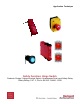
Application Technique Safety Function: Hinge Switch Products: Ensign 3 Hinge Interlock Switch, Guardmaster Dual-input Safety Relay Safety Rating: CAT.
Safety Function: Hinge Switch Important User Information Read this document and the documents listed in the additional resources section about installation, configuration, and operation of this equipment before you install, configure, operate, or maintain this product. Users are required to familiarize themselves with installation and wiring instructions in addition to requirements of all applicable codes, laws, and standards.
Safety Function: Hinge Switch 3 General Safety Information Contact Rockwell Automation to find out more about our safety risk assessment services. IMPORTANT This application example is for advanced users and assumes that you are trained and experienced in safety system requirements. ATTENTION: Perform a risk assessment to make sure all task and hazard combinations have been identified and addressed. The risk assessment can require additional circuitry to reduce the risk to a tolerable level.
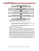
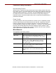
Safety Function: Hinge Switch From: Risk Assessment (ISO 12100) 1. Identification of safety functions 2. Specification of characteristics of each function 3. Determination of required PL (PLr) for each safety function To: Realization and PL Evaluation Hinge Interlock Switch Safety Function This safety function application technique provides two safety functions.
Safety Function: Hinge Switch 5 Functional Safety Description Door Monitoring Function When the door is opened, the hinge switch opens its two safety contacts. When the hinge switch turns off, the Guardmaster dual-input safety relay (GSR DI) responds by opening its safety contacts (13...14 and 23…24), de-energizing the coils of K1 and K2. With power removed, hazardous motion coasts to a stop (Stop Category 0).
Safety Function: Hinge Switch Setup and Wiring For detailed information on installing and wiring, refer to the publications listed in the Additional Resources. System Overview The Ensign 3 hinge switch is a hinge-actuated safety interlock switch, designed to fit at the hinge-point of guards. With its rotatable head, the versatile Ensign 3 switch offers four mounting options. The operation of the unit is achieved by the hinging action of the guard.
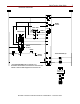
Safety Function: Hinge Switch Electrical Schematic Status To PLC 800F-1YP8 LOGIC Status To PLC 440H-E22027 Status To PLC Reset Status To PLC 100S-C09EJ23BC (2)* * The 100S-C09EJ23BC has an electronic coil. Contactors with standard, non-electronic coils must have a diode or other suitable suppression across the coil.
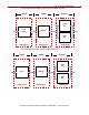
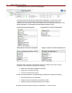
Safety Function: Hinge Switch Configuration The following procedure sets the function of the device. 1. To start configuration/overwrite: with the power off, turn the rotary switch to position 0. The unit powers up. After the power-up test, the PWD LED flashes red. 2. To set the configuration, turn the rotary switch to position 2. The IN 1 LED blinks for the new setting. Position is set when the PWR LED is solid green. 3. Lock-in the configuration by cycling unit power. 4.
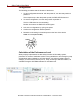
Safety Function: Hinge Switch The Door Monitoring safety function can be modeled as shown. INPUT LOGIC OUTPUT 100S K1 Hinge Switch GSR DI 100S K2 Subsystem 1 Subsystem 2 Subsystem 3 The E-stop safety function can be modeled as shown.
Safety Function: Hinge Switch Overall Safety Function’s Functional Safety Data Fault exclusion was used for the hinge switch subsystem. A PL value of d was entered manually for this subsystem. Because fault exclusion was used, this subsystem is not included in the overall safety function probability of failure per hour (PFH) calculation. This derates the overall safety function to PLd.
Safety Function: Hinge Switch 11 SISTEMA software calculates the MTTFd by using B10d data provided for the contactors along with the estimated frequency of use, entered during the creation of the SISTEMA project. The DCavg (99%) for the contactors is selected from the Output Device table of EN ISO 13849-1 Annex E, Direct Monitoring. The DCavg (99%) for the hinge switch is selected from the Input Device table of EN ISO 13849-1 Annex E, Cross Monitoring.
Safety Function: Hinge Switch GSR Hinge Switch Safety Function Verification and Validation Checklist General Machinery Information Machine Name/Model Number Machine Serial Number Customer Name Test Date Tester Name(s) Schematic Drawing Number Guardmaster Safety Relay Model Safety Wiring and Relay Configuration Verification Test Step Verification Pass/Fail Changes/Modification Visually inspect the safety relay circuit to verify that it is wired as documented in the schematics.
Safety Function: Hinge Switch 13 GSR Hinge Switch Safety Function Verification and Validation Checklist (continued) Abnormal Operation Validation The safety relay system properly responds to all foreseeable faults with corresponding diagnostics. Hinge Switch Input Tests Test Step Validation Pass/Fail Changes/Modification While the system is running, remove the channel 1 wire from the safety relay. Both contactors de-energize. Verify proper machine-status indication and safety-relay status indication.
Safety Function: Hinge Switch GSR Emergency Stop Safety Function Verification and Validation Checklist (continued) General Machinery Information Machine Name/Model Number Machine Serial Number Customer Name Test Date Tester Name(s) Schematic Drawing Number Guardmaster Safety Relay Model Safety Wiring and Relay Configuration Verification Test Step Verification Pass/Fail Changes/Modification Visually inspect the safety relay circuit to verify that it is wired as documented in the schematics.
Safety Function: Hinge Switch 15 GSR Emergency Stop Safety Function Verification and Validation Checklist (continued) Abnormal Operation Validation The safety relay system properly responds to all foreseeable faults with corresponding diagnostics. E-stop Input Tests Test Step Validation Pass/Fail Changes/Modification While the system is running, remove the channel 1 wire from the safety relay. Both contactors de-energize. Verify proper machine-status indication and safety-relay status indication.
Safety Function: Hinge Switch Additional Resources Refer to these publications for more information about related products from Rockwell Automation. Resource Description Sprite & Ensign 3 Installation Instructions, publication 440H-IN001 Provides guidance on installing, commissioning, operating, and maintaining the hinge switch. Guardmaster Safety Relay DI Installation Instructions, publication 10000175129 ver.