
Troubleshooting Guide Manual

4-4
SA500 Diagnostics, Troubleshooting, and Start-Up Guidelines
4.6 Basic Drive Interconnections
The SA500 drive requires interconnecting wiring per applicable codes between the
drive and the following:
•
motor
•
operator’s control station (if used)
•
resolver
•
UDC module
•
earth ground
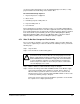
Refer to the Elementary Diagram (W/E) (and the Interconnection Diagram (W/I) if
provided) supplied with your drive for these interconnections. Be sure that the W/E
number corresponds to that on the drive’s cabinet or Power Module nameplate. All
interconnecting wiring must be sized and installed in conformance with the National
Electrical Code and applicable local or other codes.
Unless a standard pre-built fiber-optic cable was included with your system, the
fiber-optic cabling that links the UDC module(s) in the AutoMax rack with the Power
Module(s) containing the PMI(s) must be installed by someone experienced in
installing fiber-optic cables. Unless you have in-house expertise in installing fiber-optic
cable, it is recommended that you contact an experienced contractor to perform the
installation. Information regarding the selection and installation of fiber-optic cabling is
contained in the Distributed Power System Fiber-Optic Cabling instruction manual
(S-3009).
4.7 Drive Inspection and Start-up Guidelines
!
!
DC bus capacitors retain hazardous voltages after input
power has been disconnected. After disconnecting input power from the
DC bus supply, wait five (5) minutes and then measure the voltage at the
POS and NEG terminals of the DC bus supply and each Power Module
to ensure the DC bus capacitors are discharged before touching any
internal components. Failure to observe this precaution could result in
severe bodily injury or loss of life.