
Owner manual


Installation Guidelines
3-9
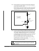
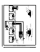
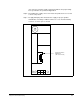
Step 4. DC bus supplies 615055-2R and 615055-2S are supplied with built-in braking
resistors to dissipate power that is regenerated by the motor. The 50A bus
supply has one braking resistor, while the 100A bus supply has two. See
table 3.5. for internal resistor specifications.
If the motor is to be operated in the regenerative mode, the application’s
regenerative power dissipation requirements should be evaluated. A DC bus
supply using external braking resistors (615055-2T or 615055-2V) may be
needed to increase the bus supply’s power dissipation capacity. To calculate
the proper resistor values, refer to the procedures in section 3.2.
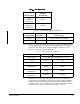
DC Bus Supply
Maximum Input Fuse
UL Class
RK5 250 VAC
50A
(615055-2R)
(615055-2T)
40 Amp
100A
(615055-2S)
(615055-2V)
90 Amp
Table 3.4 – Minimum/Maximum Input Wire Sizes
DC Bus Supply
Current Rating Terminals
Minimum/Maximum Wire Sizes
(mm2 / gauge)
50A
L1, L2, L3
4.8 to 21.6 mm
2
(10 - 4 AWG)
100A
L1, L2, L3
13.6 to 35 mm
2
(6 - 2AWG)
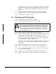
Table 3.5 – Internal Braking Resistor Specifications
Resistor Specifications 50A Bus Supply 100A Bus Supply
Trigger Voltage 1.47 ∗ RMS input line voltage (V
LL
) + 5 volts
Ohms 8 Ω 4 Ω
Watts 600 W 1200 W
Continuous
Braking Power
414 W 1200 W
0.5 Second Overload
Braking Power
1568 W 4624 W
Instantaneous Overload
Braking Power
19,500 W 39,000 W