
Owner manual


3-4
SA500 DC Bus Supply
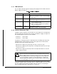
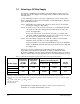
For intermittent duty the external braking resistor power dissipation is
specified by:
Maximum Fuse Current is the level of current that will cause the braking fuse
to melt in 2 seconds, as indicated on the KLK fuse rating curves. Use 14
amps for an 8 amp fuse, and 85 amps (maximum regenerative current with
4 ohms) for a 30 amp fuse.
Note:
3.3 Wiring
To reduce the possibility of electrical noise interfering with the proper operation of the
drive system, exercise care when installing the wiring between the system and
external devices. For detailed recommendations, refer to IEEE 518.
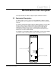
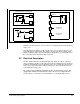
3.4 Grounding
The grounding stud (GND) on the DC bus supply must be connected externally to
earth ground (PE) as shown in figure 3.3 on page 3-8 and checked with an ohmmeter
before power is applied. Use a star washer (toothed lock washer) on the grounding
stud to ensure continuity.
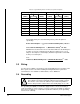
Table 3.2 – Typical Braking Resistor Continuous Duty Power Dissipation
50 Amp Supply 8 Amp Fuse 100 Amp Supply 30 Amp Fuse
R
(ohms)
τ
(seconds)
Max CBP
(watts)
R
(ohms)
τ
(seconds)
Max CBP
(watts)
8 0.03 414 4 0.10 2916
16 0.11 829 6 0.22 4374
24 0.25 1244 8 0.40 5832
32 0.45 1658 10 0.62 7290
40 0.71 2073 12 0.89 8748
47.6
1
1. Maximum continuous power resistor value
1.0/Cont 2468
12.7
1
1.0/Cont 9258
48 Continuous 2451 14 Continuous 8403
55 Continuous 2139 15 Continuous 7843
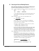
Resistor Power Dissipation =
x (0.5 Second Overload Braking Power) watt-secs
1
/
2
0.5 Second Overload Braking Power = (Maximum Fuse Current)
2
x R watts
Instantaneous Maximum Braking Power =
(Maximum DC Bus Voltage)
2
R
watts
!
ATTENTION:
Ungrounded equipment presents a shock hazard. If your
drive cabinet is mounted such that the cabinet is not grounded, a ground
wire must be connected to the cabinet for personnel safety. Failure to
observe this precaution could result in severe bodily injury or loss of life.