Distributed Power System SA500 DC Bus Supply 615055-2R (50 Amp) 615055-2T (50 Amp) 615055-2S (100 Amp) 615055-2V (100 Amp) Instruction Manual S-3017-1
Throughout this manual, the following notes are used to alert you to safety considerations: ! ATTENTION: Identifies information about practices or circumstances that can lead to personal injury or death, property damage, or economic loss. Important: Identifies information that is critical for successful application and understanding of the product. The thick black bar shown on the left margin of this paragraph will be used throughout this manual to signify new or revised text or figures.
CONTENTS Chapter 1 Introduction 1.1 Related Publications ........................................................................................ 1-2 1.2 Related Hardware............................................................................................ 1-2 Chapter 2 Mechanical/Electrical Description 2.1 Mechanical Description ................................................................................... 2-1 2.1.1 LED Indicators...............................................................
II SA500 DC Bus Supply
List of Figures Figure 2.1 – SA500 DC Bus Supply Faceplate......................................................... 2-1 Figure 2.2 – Circuitry of Terminals 1 and 2 of Interface Connector TB1 .................. 2-3 Figure 3.1 – SA500 DC Bus Supply Mounting Dimensions...................................... 3-6 Figure 3.2 – Jumper W1 ........................................................................................... 3-7 Figure 3.3 – SA500 DC Bus Supply Wiring ............................................
IV SA500 DC Bus Supply
List of Tables Table 1.1 – SA500 DC Bus Supplies........................................................................ 1-1 Table 1.2 – SA500 Documentation (Binder S-3002) ................................................ 1-2 Table 2.1 – Faceplate LED Indicators ...................................................................... 2-2 Table 3.1 – SA500 DC Bus Supply Motoring Current and Internal Power Dissipation Specifications ...................................... 3-2 Table 3.
VI SA500 DC Bus Supply
CHAPTER 1 Introduction Distributed Power System (DPS) SA500 DC Bus Supplies rectify three-phase AC input voltage and provide constant DC voltage to the SA500 AC Power Modules. The DC bus supplies also contain circuits that permit regeneration from the SA500 AC Power Modules during motor deceleration or overhauling. The main circuit, which supplies motoring current, consists of a full-wave bridge made from three SCRs in the upper legs and three diodes in the lower legs.
1.1 Related Publications This instruction manual provides a description of the SA500 DC bus supply hardware. Installation and troubleshooting guidelines are also provided. Note that this instruction manual does not describe specific applications of the standard hardware or software. For more information, refer to the instruction manuals contained in the SA500 drive binder, S-3002, as listed in table 1.2.
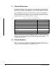
CHAPTER 2 Mechanical/Electrical Description This chapter describes the DC bus supply’s faceplate and internal electronics. 2.1 Mechanical Description The DC bus supply consists of a phase-controlled SCR bridge, a DC bus regulator, DC bus capacitors, and cooling fan(s). The components are housed in a sheet metal enclosure. The regulator circuit board assembly contains the LEDs and interface connector (TB1) which are visible on the bus supply’s faceplate.
2.1.1 LED Indicators The four LEDs visible through the faceplate provide diagnostics information about the DC bus supply. See table 2.1.
INTERFACE CONNECTOR TB1 SAMPLE EXTERNAL CONNECTIONS 1 1 2 2 STATUS- +V COM STATUS+ 3 Not Supported Do Not Use 4 Not Supported Do Not Use 1 +V COM 2 Figure 2.2 – Circuitry of Terminals 1 and 2 of Interface Connector TB1 Terminals 3 and 4 of interface connector TB1 are not supported at this time and must not be used. Note that jumper W1, which is visible only when the cover is removed, must be set to position B (factory setting) for the bus supply to operate correctly. See figure 3.
2-4 SA500 DC Bus Supply
CHAPTER 3 Installation Guidelines This chapter provides guidelines for installing and replacing the SA500 DC bus supply. Instructions are included describing how to select a bus supply based on the bus supply’s current rating and the combined current draw of the motors attached to the bus supply through the SA500 AC Power Modules.
3.1 Selecting a DC Bus Supply The number of SA500 AC Power Modules that a single DC bus supply can power depends upon the bus supply’s current rating and the combined current draw of the attached motors. Use the following procedure to select a bus supply based on motor current values. Refer to Appendix C for motor current information on Industrial Brushless, Brushless Servo, and Induction motors. Step 1. Add together the continuous Idc currents of all the motors to be powered from the bus supply.
3.2 Selecting an External Braking Resistor DC bus supplies with external braking resistors (615055-2T or 615055-2V) allow for greater power dissipation during motor regeneration. Perform the following steps to determine the required external braking resistor specifications. Step 1.
Table 3.2 – Typical Braking Resistor Continuous Duty Power Dissipation 50 Amp Supply R (ohms) 8 Amp Fuse τ 100 Amp Supply 30 Amp Fuse τ (seconds) Max CBP (watts) R (ohms) (seconds) Max CBP (watts) 8 0.03 414 4 0.10 2916 16 0.11 829 6 0.22 4374 24 0.25 1244 8 0.40 5832 32 0.45 1658 10 0.62 7290 40 0.71 2073 12 0.89 8748 47.61 1.0/Cont 2468 12.71 1.0/Cont 9258 48 Continuous 2451 14 Continuous 8403 55 Continuous 2139 15 Continuous 7843 1.
3.5 DC Bus Supply Initial Installation The following procedure is intended to be only a guide to assist you in installing the DC bus supply. Refer to the wiring diagrams supplied with you system for more specific information. Step 1. Mount the DC bus supply. DC bus supplies are designed to be mounted on a flat surface using M5 or #10 screws. The holes in the top flange are key-hole shaped and the lower holes are U-shaped to facilitate mounting.
Figure 3.1 – SA500 DC Bus Supply Mounting Dimensions 3-6 SA500 DC Bus Supply Typical 115 mm (4.5") B 1 B SA500 AC Power Module 1/4 Turn Cover Fasteners SA500 DC Bus Supply #10 (M5) Mounting Screws SA500 AC Power Module B Front View 2 Mounting Screw Head Diameter is 10 mm (0.39") maximum Covers are removed by pulling them straight out as indicated by arrow A = 102 mm (4") minimum B = 118 mm (4.62") minimum, 127 mm (5") maximum C = 13 mm (0.5") minimum 1 35 mm (1.
Step 2. Rotate the quarter-turn cover fasteners and remove the bus supply’s front cover. Check the bus supply’s nameplate to ensure that the bus supply has the proper power rating (50A or 100A). Examine jumper W1 on the printed circuit board (see figure 3.2). The jumper must be set to position B for the bus supply to operate properly. This is the factory setting. When the jumper is set to position B, the bus supply will be enabled whenever the correct three-phase input voltage is present.
Figure 3.3 – SA500 DC Bus Supply Wiring 3-8 SA500 DC Bus Supply U V W M6 Nut Terminal Post Base U V W Fuse Fuse Fuse GND 47 48 Drive or Power Supply Bus Bar Flat Washers L1 L2 L3 SA500 DC Bus Supply POS NEG Lock Washers Positive and Negative Terminals M6 Terminal Post PE Connecting Lugs To Grounding Rod or Building Steel POS NEG SA500 AC Power Module Fuse Disconnecting Switch GND Short Circuit Capacity 5000 Amps or Less AC Input Voltage (3-Phase) *Wires are 225 mm (8.
7DEOH ¤ 6KRUW &LUFXLW 3URWHFWLRQ Maximum Input Fuse UL Class RK5 250 VAC DC Bus Supply 50A (615055-2R) (615055-2T) 40 Amp 100A (615055-2S) (615055-2V) 90 Amp Table 3.4 – Minimum/Maximum Input Wire Sizes DC Bus Supply Current Rating Terminals Minimum/Maximum Wire Sizes (mm2 / gauge) 50A L1, L2, L3 4.8 to 21.6 mm2 (10 - 4 AWG) 100A L1, L2, L3 13.6 to 35 mm2 (6 - 2AWG) Step 4.
If external resistors are to be used, connect the wires from the resistors to the terminal block at the top of the bus supply. A notch in the front cover allows the wires to be routed from the terminal block even when the front cover is installed. Step 5. Apply power to the input wiring and check that the voltages are within operating parameters. Voltage specifications are given in Appendix A. Step 6. Re-attach the bus supply’s front cover. 3.
CHAPTER 4 Diagnostics and Troubleshooting ! ATTENTION: DC bus capacitors retain hazardous voltages after input power has been disconnected. After disconnecting input power from the DC bus supply, wait five (5) minutes and then measure the voltage at the POS and NEG terminals of the DC bus supply and each Power Module to ensure the DC bus capacitors are discharged before touching any internal components. Failure to observe this precaution could result in severe bodily injury or loss of life.
4.1.3 The PSM READY LED Is Off Problem: The DC bus voltage is different from what is expected. During normal operation, the PSM READY LED is on when AC power is applied and there are no bus supply faults. If this LED turns off, use the following procedure to isolate the problem: Step 1. Using a voltmeter, verify that the DC bus supply is receiving the correct AC input voltage (terminals L1, L2, L3). Step 2. If the bus supply is not receiving the correct input voltage, check the AC input power lines.
open. If the fuse is blown, install a replacement that has the proper ratings. Fuse specifications are provided in Appendix A. Step 6. Re-install the bus supply’s front cover. Rotate the quarter-turn cover screws to the closed position. Step 7. Re-apply AC input power and test the bus supply for proper operation. If the DC bus overvoltage condition continues to occur, check the braking resistor to see if it is open or shorted. Replaceable DC Bus Braking Fuse (with cover removed) Figure 4.
4-4 SA500 DC Bus Supply
APPENDIX A Technical Specifications Ambient Conditions • Operating Temperature: 0 to 50° C (32 to 122° F) • Relative Humidity: 5 to 95% (non-condensing) Dimensions • Height: 445 mm (17.5 in) • Width: 115 mm (4.5 in) • Depth: 250 mm (9.8 in) • Weight: 11.9 kg (26.
Internal Braking Resistor Instantaneous Overload Power Dissipation • 50A units: 19,500W • 100A units: 39,000W DC Bus Braking Fuse • DC Bus Supply (50A) with Internal Braking Resistor: Littelfuse KLK D8, Fast Acting, 600V, 8A or Bussman KLM-8 • DC Bus Supply (50A) with External Braking Resistor: Littelfuse KLK D8, Fast Acting, 600V, 8A or Bussman KLM-8 • DC Bus Supply (100A) with Internal Braking Resistor: Littelfuse KLK D20, Fast Acting, 600V, 20A or Bussman KLM-20 • DC Bus Supply (100A) with External
APPENDIX B Block Diagram Fuse Resistor 230 VAC Input Voltage Resistor DC-to-DC Power Supply Block Diagram Pre-charge SCR Driver Voltage Feedback DC Bus Output Voltage to SA500 AC Power Module Braking Transistor Driver LEDs B-1
B-2 SA500 DC Bus Supply
APPENDIX C Motor Current Specifications Table C.1 – Industrial Brushless Motors Model No. HP Max Speed RPM Encl Cont Iac RMS Amps Cont Idc Amps (Bus Supply Requirement) Max Iac RMS Amps Max Idc Amps (Bus Supply Requirement) Min DC Bus Supply B14H3050 1 2000 TENV 3.3 4.2 6.5 8.2 1 B14H3060 2 2000 TENV 6.5 8.2 13.1 16.5 1 B18H3070 3 2000 TENV 9.8 12.4 19.6 24.7 1 B18H3080 4 2000 TENV 13.1 16.5 26.3 33.2 1 P21M0309 7.5 1750 TENV 24.0 30.3 48.0 60.
Table C.3 – Induction Motors Model No. HP Max Speed RPM Encl Cont Iac RMS Amps Cont Idc Amps Max Iac (Bus Supply RMS Requirement) Amps Max Idc Amps (Bus Supply Requirement) Min DC Bus Supply P14A5810 1 1757 TENV 3.0 3.8 4.5 5.7 1 P14A5804 1.5 1756 TENV 4.4 5.5 6.6 8.3 1 P14A5813 2 1764 TENV 5.8 7.3 8.7 11.0 1 P18A6111 3 1758 TENV 9.0 11.3 13.5 17.0 1 P18A6113 5 1737 TENV 14.4 18.2 21.6 27.2 1 P21L0212 5 1781 TENV 15.3 19.3 23.0 28.
APPENDIX D Compliance with Electromagnetic Compatibility Standards D.1 Introduction This appendix provides information on the SA500 DC Bus Supplies and AC Power Modules’ compliance with European Community electromagnetic compatibility (EMC) standards and covers the following: • requirements for standards compliance • guidelines on installing the equipment • instructions on how the drive must be wired.
D.3 Installing the Equipment The equipment must be mounted inside a steel cabinet. The cabinet door must be grounded to the main cabinet. Any accessory plates attached to the cabinet door must be grounded to the same point on the cabinet as the door. The cabinet must also have floor pans with the cutouts for cable entries kept to an absolute minimum.
D.6.2 Rail Ports The two rail Rail Ports must not be used for CE applications. As an alternative, digital I/O can be configured using either the digital I/O on the Resolver and Drive I/O Module or the Allen-Bradley Remote I/O Interface Module (M/N 57C443) and Allen-Bradley I/O. D.6.3 Resolver and Analog Input Wiring Resolver cable M/N 417900-207CG is recommended.
Figure D.
INDEX B Block diagram, B-1 Braking fuse checking for a blown fuse, 4-2 to 4-3 fuse location, 4-3 Braking resistor external braking resistor, 3-3 to 3-4 internal braking resistor specifications, 3-9 C Compliance with electromagnetic compatibility standards, D-1 to D-4 selecting a DC bus supply, 3-2 selecting an external braking resistor, 3-3 to 3-4 short circuit protection, 3-9 wiring, 3-4, 3-8 Interface connector TB1, 2-2 to 2-3 circuitry of terminals 1 & 2, 2-3 Internal power dissipation specifications,
Index-2 SA500 DC Bus Supply
DIF Documentation Improvement Form Use this form to give us your comments concerning this publication or to report an error that you have found. For convenience, you may attach copies of the pages with your comments. After you have completed this form, please return it to: Rockwell Automation RGA (Technical Publications) 25001 Tungsten Road Cleveland, Ohio 44117 Fax: 216.266.
Rockwell Automation / 24703 Euclid Avenue / Cleveland, Ohio 44117 / (216) 266-7000 Printed in U.S.A.