
Manual


Installation Guidelines
4-3
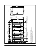
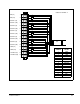
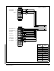
Figure 4.1 – Power Module Mounting Dimensions
SA500
Module
DC Bus
Supply
SA500
Module
Front View
B B B B C
C
35 mm
(1.38")
35 mm
(1.38")
Typical
115 mm
(4.5")
#10 (M5)
Mounting Screws
1/4 Turn Cover
Fasteners
Minimum Recommended
Panel Space Requirement
A
A
7 mm
(0.27)
12 mm
(0.47")
411 mm
(16.18")
429 mm
(16.88")
243 mm
(9.5")
Side View
Air Exhaust
Air Intake
445 mm
(17.5")
SA500
SA500
Module
SA500
AC Power
Module
Mounting Screw Head Diameter is 10 mm (0.39") maximum
Covers are removed by pulling them straight out as indicated by arrow
1
2
A = 102 mm (4") minimum
B = 118 mm (4.62") minimum, 127 mm (5") maximum
C = 13 mm (0.5") minimum
1
2
AC Powe
r
AC Power AC Power