Distributed Power System SA500 AC Power Modules 615055-1R (14 Amp) 615055-1S (28 Amp) 615055-1T (35 Amp) 615055-1V (48 Amp) Instruction Manual S-3018-1
Throughout this manual, the following notes are used to alert you to safety considerations: ! ATTENTION: Identifies information about practices or circumstances that can lead to personal injury or death, property damage, or economic loss. Important: Identifies information that is critical for successful application and understanding of the product. The thick black bar shown on the left margin of this paragraph will be used throughout this manual to signify new or revised text or figures.
CONTENTS Chapter 1 Introduction 1.1 Distributed Power System (DPS) Overview .................................................... 1-2 1.2 SA500 Drive Overview .................................................................................... 1-3 1.3 Related Publications ........................................................................................ 1-4 Chapter 2 Power Module Mechanical Description 2.1 LED Indicators ...............................................................................
Appendix E Status of Data in the AutoMax Rack After a STOP_ALL Command or STOP_ALL Fault ............................................................. E-1 Appendix F PMI Regulator Block Diagram.................................................................................. F-1 Appendix G Power Circuitry Block Diagram ................................................................................G-1 Appendix H Compliance with Electromagnetic Compatibility Standards .....................................
List of Figures Figure 1.1 – SA500 Drive Hardware Configuration .................................................. 1-2 Figure 2.1 – SA500 Power Module With Cover and Without Cover ......................... 2-2 Figure 2.2 – Power Module External Connectors ..................................................... 2-6 Figure 2.3 – Location of Rail Fuse on PMI Regulator PC Board .............................. 2-8 Figure 2.4 – Resolver Feedback Connector Pinout..................................................
IV SA500 Power Modules
List of Tables Table 1.1 – SA500 Power Modules .......................................................................... 1-1 Table 1.2 – SA500 Documentation (Binder S-3002) ................................................ 1-4 Table 4.1 – Recommended Motor Wire Sizes .......................................................... 4-4 Table 4.2 – Rail I/O Instruction Manuals................................................................... 4-8 Table 4.3 – Standard Resolver Connections ...........................
VI SA500 Power Modules
CHAPTER 1 Introduction The AutoMax Distributed Power System SA500 AC Power Modules provide AC power to, and control of, brushless motors and squirrel-cage induction motors from 1–15HP. Each Power Module contains the Power Module Interface (PMI) Regulator printed circuit board and the inverter used to convert DC power to AC power for the motor.
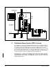
AC Line Universal Drive Controller Module SA500 DC Bus Supply AutoMax Rack SA500 Power Module Fiber-Optic Link (up to 750 m) Resolver Drive I/O Motor Digital Rail Analog Rail Resolver Feedback Figure 1.1 – SA500 Drive Hardware Configuration 1.1 Distributed Power System (DPS) Overview The SA500 is a member of the AutoMax Distributed Power System (DPS) family of drives. DPS is a programmable microprocessor-based control system that is capable of real-time control of AC and DC drives.
1.2 SA500 Drive Overview An SA500 drive consists of a DC Bus Supply and a Power Module which supplies three-phase AC power to an induction motor or a permanent magnet brushless motor. The SA500 DC Bus Supply rectifies three-phase 230 VAC power to provide a constant DC voltage for the Power Module. A three-phase bridge consisting of three SCRs and three diodes controls the currents during charging of the DC bus capacitor.
1.3 Related Publications This instruction manual provides a description of the SA500 Power Module hardware. Installation guidelines are also provided. Note that this instruction manual does not describe specific applications of the standard hardware or software. For more information, refer to the instruction manuals contained in the SA500 drive binder, S-3002, as listed in table 1.2.
CHAPTER 2 Power Module Mechanical Description Power Modules of all four ratings are the same size, consisting of a sheet metal enclosure, cooling fans, heatsink, a power supply PC board, inverter power devices, and the PMI Regulator PC board. A DC-to-DC converter supplies power to the PMI and to Hall-effect devices used for current feedback.
PWR OK OK COMM OK P.M. FLT EXT FLT RAIL FLT FDBK OK RPI MCR AUX IN1 AUX IN2 AUX IN3 AUX IN4 AUX IN5 AUX OUT RE-BOOT P1 XMT COMM LINK RCV P2 P3 RAIL PORT 0 P4 RAIL PORT 1 P5 RESOLVER FEEDBACK P6 DRIVE I/O WITH COVER ON WITH COVER REMOVED Figure 2.
2.1 LED Indicators The LEDs on the faceplate of the Power Module indicate the status of the PMI, inverter, fiber-optic link, rail I/O, resolver feedback signal, and drive I/O. The status of the LEDs is also reported in the UDC module’s dual port memory. See the SA500 Drive Configuration and Programming instruction manual (S-3044) for a complete description of the following status bits.
EXT FLT (red) - When lit, this LED indicates that one of the following external fault conditions has occurred: • Overcurrent fault Corresponding UDC location: Register 202/1202, bit 1 • User-programmed fault Corresponding UDC location: Register 101/1101, bit 2 • Overspeed fault Corresponding UDC location: Register 202/1202, bit 10 RAIL FLT (red) - When lit, this LED indicates communication between an I/O rail and the PMI has been disrupted, or that a rail has been configured but is not plugged in.
AUX IN1 (green) - When lit, this LED indicates the presence of a 115 volt signal on this input (pin C). This LED is used for M-contactor feedback when the programmer has configured an output contactor between the Power Module and the motor. The use of an M-contactor is optional. Corresponding bit location: Register 201/1201, bit 1. AUX IN2 (green) - When lit, this LED indicates the presence of a 115 volt signal on this input (pin E). Corresponding bit location: Register 201/1201, bit 2.
2.2 Power Module Faceplate Connectors The following sections describe the Power Module faceplate connectors. Figure 2.2 shows the external connections to the Power Module. PS PWR OK OK COMM OK P.M.
2.2.1 Fiber-Optic Ports Transmit (XTM) and receive (RCV) ports are provided on the faceplate of the Power Module for connection to the fiber-optic link with the UDC module in the AutoMax rack. The Power Module is shipped with dust caps covering the fiber-optic ports. To prevent dust accumulation and the resulting loss of signal integrity, the dust caps should not be removed until the fiber-optic cables are installed, and should be replaced if the cables are disconnected.
RIGHT SIDE VIEW FAN POWER RAIL FUSE Figure 2.3 – Location of Rail Fuse on PMI Regulator PC Board 2.2.3 Resolver Feedback Connector The faceplate connector labeled “RESOLVER FEEDBACK” is used to connect the resolver to the Power Module. This connector will also accept a signal from an analog tachometer or other analog field device as long as the signal is within the correct voltage range. (Note that the tachometer cannot be used for speed feedback.
! ATTENTION: For brushless motor applications, changing any resolver wiring, breaking the resolver coupling, replacing the resolver, or replacing the motor and resolver for any reason requires that the shaft alignment test be performed again. Resolver wiring changes always affect shaft alignment. A resolver change and/or a new motor/resolver combination will affect the shaft alignment. Improper shaft alignment can cause motor overspeed when the motor is started.
312K 1.04M +15 V ANALOG TO A/D SUBSYSTEM 20K – + ANALOG+ 5600 pF 1.04M AGND 312K ANALOG SHIELD THESE COMPONENTS ARE ON THE PMI REGULATOR THIS CONNECTION IS MADE WITH THE DC/DC CONVERTER AGND 1K AGND -15 V 10K .33 µF .33 µF DGND DGND AGND Figure 2.5 – Analog Input Circuit 2.2.
If any of these events occurs, the PMI will wait for 100 msec and then turn off the MCR output. If the RPI signal is removed, the MCR output will be turned off and gate power will be removed under hardware control within approximately 0.5 second to provide an additional level of protection. The user has the option of having an M-contactor (i.e., an output contactor) on the output of the Power Module. This option is available during UDC parameter configuration.
Figure 2.
CHAPTER 3 Power Module Electrical Description DC input voltage to the Power Module is supplied by a DC bus, normally the SA500 DC Bus Supply. The inverter bridge in the Power Module converts the constant potential DC voltage from the DC bus to three-phase AC power for the motor. The inverter bridge consists of six bi-polar transistors. Interlock circuitry ensures that the upper phase and lower phase U, V, and W transistors are never turned on at the same time.
The PMI will automatically request its operating system from the UDC module as soon as communications are established over the fiber-optic link. After the operating system has been downloaded from the UDC module (a process that takes approximately 0.5 seconds), the PMI Regulator will send a feedback message. The UDC module will respond with a command message and configuration data.
bits 15 14 13 12 11 10 9 8 7 6 5 4 3 2 1 0 resolver data revolution counter Figure 3.2 – Resolver Data Format (14-Bit Mode) The PMI produces a nominal 26 volt rms 2381 Hertz sine wave reference output signal which is capable of driving a 500 ohm load. The stator signals (sine and cosine) are input through a matched isolation transformer pair. The transformers are matched for gain and phase shift. The ratio of the sine and cosine amplitudes is then converted to an angular position.
24 V NOM EXT. STROBE INPUT RESOLVER POSITION LATCH COMMAND Td Td Tpw Tper Td - 250 mSEC TYP. Tpw - 300 mSEC MIN. Tper - 1000 mSEC MIN. Figure 3.4 – External Strobe Input Circuit Timing Diagram Strobe input detection is enabled by setting bits 8 and/or 9 in UDC register 101/1101. The resolver position can be sampled on the strobe input's rising edge, falling edge, or both. Latched data is sent to the UDC module immediately before it is needed by the UDC module for the next UDC task scan.
CHAPTER 4 Installation Guidelines ! ATTENTION: Only qualified personnel familiar with the construction and operation of this equipment and the hazards involved should install, adjust, operate, or service this equipment. Read and understand this manual and other applicable manuals in their entirety before proceeding. Failure to observe this precaution could result in severe bodily injury or loss of life. ATTENTION: DC bus capacitors retain hazardous voltages after input power has been disconnected.
Step 1. Mount the Power Module. Power Modules are designed to be mounted vertically on a flat surface using M5 or #10 screws. The holes in the top flanges are key-hole shaped and the lower hole is U-shaped to facilitate mounting. The Power Module should be mounted in a location with good air flow and must be in close proximity to the DC Bus Supply. Power Modules should not be mounted one over another because the exhaust air from the lower Power Module would feed the air intake of the upper Power Module.
Figure 4.1 – Power Module Mounting Dimensions Installation Guidelines 4-3 Typical 115 mm (4.5") B 1 B SA500 AC Power Module 1/4 Turn Cover Fasteners SA500 DC Bus Supply #10 (M5) Mounting Screws SA500 AC Power Module B Front View 2 Mounting Screw Head Diameter is 10 mm (0.39") maximum Covers are removed by pulling them straight out as indicated by arrow A = 102 mm (4") minimum B = 118 mm (4.62") minimum, 127 mm (5") maximum C = 13 mm (0.5") minimum 1 35 mm (1.
! ATTENTION: To avoid the danger of an electrical shock or burn, only qualified personnel should install or service this equipment. Disconnect all power before working on this equipment. Dangerous voltages may exist after power is removed. Check the DC Bus Supply voltages each time power is removed before servicing. Failure to observe this precaution could result in severe bodily injury or loss of life. Step 2. Connect the DC bus wires (POS, NEG, GND) from the DC Bus Supply to the Power Module.
Figure 4.2 – DC Bus Supply Wiring Installation Guidelines 4-5 U V W M6 Nut Terminal Post Base U V W Fuse Fuse Fuse GND 47 48 Drive or Power Supply Bus Bar Flat Washers L1 L2 L3 SA500 DC Bus Supply POS NEG Lock Washers Positive and Negative Terminals M6 Terminal Post PE Connecting Lugs To Grounding Rod or Building Steel POS NEG SA500 AC Power Module Fuse Disconnecting Switch GND Short Circuit Capacity 5000 Amps or Less AC Input Voltage (3-Phase) *Wires are 225 mm (8.
4.3 Fiber-Optic Connection ! ATTENTION: Turn off, lock out, and tag power to both the rack containing the UDC module and to its corresponding PMI hardware before viewing the fiber-optic cable or transmitter under magnification. Viewing a powered fiber-optic transmitter or connected cable under magnification may result in damage to the eye. For additional information refer to ANSI publication Z136.1-1981. Failure to observe this precaution could result in bodily injury.
Cable No.
4.5 Rail Port Connection Analog and digital I/O rails are connected to the Power Module using an I/O Interconnect Cable (M/N 45C5). Refer to the appropriate instruction manual for the installation and wiring procedures for your equipment. See table 4.2. Table 4.2 – Rail I/O Instruction Manuals Model No. 4.
Cable No. 612426-S ANALOG INPUT (+) 1 1 ANALOG INPUT (–) 2 2 SHIELD 3 3 4 5 6 ANALOG REFERENCE OUT (+) 1 1 REFERENCE OUT (–) 2 2 SINE INPUT (+) 3 3 SINE INPUT (–) 4 4 COSINE INPUT (+) 5 5 COSINE INPUT (–) 6 6 EXT. TRIGGER (+) 7 777 EXT. TRIGGER (–) 8 8 RESOLVER 9 10 WIRE NUMBER WIRE COLOR ANALOG 1 BLK 2 CLEAR 3 DRAIN (SHIELD) RESOLVER 1 BRN 2 WHT/BRN 3 RED 4 WHT/RED 5 ORG 6 WHT/ORG 7 YEL 8 WHT/YEL Figure 4.
4.6.1 Resolver Input Connections The resolver input connections are shown in table 4.3. Note that Distributed Power Systems are designed to be used with the standard resolvers listed in this table 4.3 and in Appendix A. Table 4.3 – Standard Resolver Connections Resolver Resolver & Drive I/O Module Connector Pin Resolver Winding 613469-1,-2 800123, 800123-1 800123-2 TB Faceplate Conn Pin Resolver Module Reference Input R1+ R2– A B 1 2 A B 1 2 A B + – Ref.
4.6.1.1 Resolver Calibration The resolver input can be used with X1 and X2 resolvers with cable distances as shown in table 4.4. The PMI contains circuitry to synchronize the reference waveform to within 10 degrees of the returning waveforms. This synchronization corrects for any phase shift which can occur between the reference and stator signal (i.e., stator signals lagging the reference) due to unbalanced wire impedance. The impedance increases as the cable length increases.
Balance Calibration The balance calibration procedure is initiated by setting UDC register 101/1101, bit 6 (RES_CAL@) after turning the drive on. The procedure takes from a few seconds to one minute to complete. It must be performed while the resolver is rotating at 5 RPM minimum speed (speed does not have to be constant). The faster the resolver is turning, the faster the balance calibration procedure will be performed. Balance calibration compensates for different cable lengths or characteristics.
The result of the resolver alignment test is written to the reserved tunable RES_ALN% by the PMI. The value in the variable represents the offset. See the SA500 Drive Configuration and Programming instruction manual (S-3044) for more information about the RES_ALN% tunable variable. The alignment test is commanded by the programmer by setting bit 1 in register 100/1100. When the test is successfully completed, the PMI will set the Alignment OK bit (bit 1 in register 200/1200).
Resolver Restrictions The PMI cannot discriminate between X1 and X2 resolvers. It only detects electrical rotations. One mechanical rotation is equivalent to one electrical rotation for an X1 resolver and two electrical rotations for an X2 resolver. The practical limit of electrical speed that the module can detect is dependent both upon the resolver selected and upon the resolution selected during drive parameter configuration. See Appendix A. 4.6.
Constant Torque Operating Range Constant Power Operating Range Pt. 1 Rated Motor Torque Pt. 2 Pt. 3 Rated Motor Voltage Pt. 4 Pt. 5 Pt. 6 Pt. 7 Pt. 8 Pt. 9 Pt. 10 Motor Speed Figure 4.5 – Typical Motor Operation in the Constant Torque and Constant Power Regions Constant power capability is only available for applications using induction motors with Vector - Speed Loop Enhanced regulators. You need to select Constant Power on the Motor Data parameter entry screen to enable constant power operation.
Table 4.5 – STATOR_IZ Tunable Values Reference Point1 Speed Reference (in counts) Tunable Where the Iz Current Value is Saved 1 409 STATOR_IZ0E2% 2 1023 (at maximum speed) STATOR_IZ1E2% 3 1125 STATOR_IZ2E2% 4 1227 STATOR_IZ3E2% 5 1329 STATOR_IZ4E2% 6 1635 STATOR_IZ5E2% 7 1941 STATOR_IZ6E2% 8 2247 STATOR_IZ7E2% 9 2859 STATOR_IZ8E2% 10 4095 STATOR_IZ9E2% 1.
Step 14. Set the application’s Speed Reference equal to 1023 (reference point 2, STATOR_IZ1E2%). Do not change the value in reference point 1, STATOR_IZ0E2%. Step 15. Start the drive. The motor should come up to speed and go into stable run. Record the motor voltage. This is the base motor voltage. Step 16. Set the Speed Reference equal to 1125 (reference point 3, STATOR_IZ2E2%). Step 17.
Step 3. Disconnect the DC Bus Supply wires from the Power Module’s POS, NEG, and GND terminals. Disconnect the motor leads from the U, V, and W terminals on the Power Module. Step 4. Remove the screws that attach the Power Module to its mounting surface. Step 5. Install the replacement Power Module by reversing steps 3 and 4 above.
CHAPTER 5 Diagnostics and Troubleshooting The PMI monitors the Power Module for numerous fault and warning conditions. Faults cause the Power Module transistor gate firing signals to be turned off and bring the motor to a coast-to-rest stop. Warnings indicate problems in the Power Module and PMI, but do not shut down the drive. See Appendix D for a cross-reference of fault and warning bits and associated LEDs.
Vcc Power Supply Undervoltage (Bit 3) LED indicator: P.M. FLT Bit 3 will be set if the input to the +5V supply for the PMI Regulator drops below the necessary voltage required to maintain regulation. Error code 1019 will also be displayed in the error log of the UDC task in which the fault occurred. Position Following Error (Bit 4) LED indicator: N/A Bit 4 will set if the maximum position error exceeds the value set in the PMI Tach Loss Maximum Position Error register (register 166/1166).
UDC Run Fault (Bit 14) LED indicator: N/A Bit 14 will be set if the UDC task stops while the minor loop is running in the PMI Regulator. Error code 1014 will also be displayed in the error log of the UDC task in which the fault occurred. Communication Lost (Bit 15) LED indicator: COMM OK Bit 15 will be set if the fiber-optic communication between the PMI Regulator and the UDC module is lost due to two consecutive errors of any type.
PMI Communication Warning (Bit 15) Bit 15 will be set if a fiber-optic communication error is detected between the PMI and the UDC module. Communication errors in two consecutive messages will cause a drive fault. 5.3 Power Module Failure The SA500 Power Module has no user-serviceable parts with the exception of the rail fuse described in section 2.2.2.
APPENDIX A Technical Specifications SA500 Power Module Part Numbers and Ratings Part Number Continuous RMS Current Rating (55° C) Maximum Output Current (RMS) (0.5 seconds)1 615055-1R 14 A 17.5 A (125%) 615055-1S 28 A 35 a (125%) 615055-1T 35 A 70 A (200%) 615055-1V 48 A 106 A (220%) 1. See Appendix I.
Maximum Power Dissipation • • • • 615055-1R 14 A 120 W 615055-1S 28 A 180 W 615055-1T 35 A 275 W 615055-1V 48 A 300 W Power Module DC-to-DC Converter • Internally powered via DC Bus Supply DC Output to PMI Regulator • 5 VDC (+/- 5%) • 24 VDC (+/- 15%) • +/- 15 VDC (+/- 5%) System Power Requirements • +5 VDC @ 1500 mA (3000 mA maximum) • +15 VDC @ 300 mA • - 15 VDC @ 300 mA Fiber-Optic Port • Transmitter: 1 • Receiver: 1 • Data rate: 10 Mbd • Coding: Manchester • Protocol: HDLC (compatible
Resolver Input Specifications (Continued) • External strobe input: • Input signal: 24 volt positive pulse • Maximum pulse frequency: 1 kHz • Minimum pulse width: 300 µsec • Typical transport delay: 250 µsec Resolver Type Accuracy Max. Error Spread (Electrical) Resolver Mechanical Max. Speed 613469-1R, -2R x1 16 arc minutes 613469-1S, 2S x2 800123-R,-1R,-2R 800123-S,-1S,-2S Resolver Part No. Resolver & Drive I/O Resulting Effective Resolver Max.
Digital Input Specifications (Continued) • Isolation: input to input: 150 VAC • Input current at 115V 60 Hz: 23.5 mA • Maximum input delay @50 Hz: 35 msec • Maximum input delay @60 Hz: 26 msec Digital Output Specifications • Number of outputs: 2 • Contact rating: 2 A @ 115 VAC • Maximum operating voltage: 132 VAC • On state voltage drop at rated current: 1.5 V @ 2 A • Maximum inrush (1 sec): 5 A • Maximum continuous current: 2 A per output • Maximum leakage current: 4.
APPENDIX B Brushless Industrial Motor Data and Curves Torque (in-lb) Torque (in-lb) 1 HP 95.0 63.0 2 HP 190 200% 126 31.5 200% 63 CONTINUOUS OPERATING RANGE CONTINUOUS OPERATING RANGE (RPM) 2000 0 Torque (in-lb) 0 Torque (in-lb) 3 HP 300 189.0 (RPM) 2400 2000 2500 2000 2500 4 HP 410 200% 252 94.5 200% 126 CONTINUOUS OPERATING RANGE CONTINUOUS OPERATING RANGE (RPM) 0 2000 Torque (in-lb) 0 Torque (in-lb) 7.
Torque (in-lb) 15 HP 1200 1080 200% 540 CONTINUOUS OPERATING RANGE 0 (RPM) 1750 2400 HP Base Speed (RPM) Torque (in-lb) Inertia (lb-in-S2 B14H3050 1 2000 31.5 0.012 B14H3060 2 2000 63 0.021 B14H3070 3 2000 94.5 0.031 B14H3080 4 2000 126 0.041 P21M0309 7.5 1750 270 0.0895 P21M0310 10 1750 360 0.1268 P21M0311 15 1750 540 0.
Brushless Servo Motor Curves DM-25/S-2005 DM-35/S-3007 TORQUE 20 (lb-in) 18 2.2 TORQUE (Nm) 2.0 16 1.8 14 1.6 1.4 12 1.2 10 1.0 8 0.8 6 0.6 4 0.4 TORQUE 24 (lb-in) 22 20 18 14 12 1.5 10 1.0 0.5 2 0.2 0 0 0 2000 3000 4000 5000 2.0 16 8 6 4 2 0 1000 TORQUE 2.5 (Nm) 6000 0 0 1000 2000 SPEED (R.P.M.) 3000 4000 5000 SPEED (R.P.M.
Brushless Servo Motor Curves DM-100/S-6200 DM-50/S-6100 TORQUE 300 (lb-in) 30 TORQUE (Nm) TORQUE 600 (lb-in) 60 500 250 25 50 200 400 20 150 40 300 15 100 50 0 0 1000 2000 30 10 200 20 5 100 10 0 0 0 0 500 3000 1000 SPEED (R.P.M.) 1500 2000 2500 3000 SPEED (R.P.M.
Table B.1 – Brushless Servo Motor - Engineering Data Motor Frame Motor Model No. Stall Torque (1) S-2005 S-3007 S-3016 S-4030 S-4050 S-4075 S-6100 S-6200 S-6300 S-8350 S-8500 S-2005-K S-3007-N S-3016-N S-4030-P S-4050-P S-4075-R S-6100-Q S-6200-Q S-6300-Q S-8350-S S-8500-S -R00AD -R00AD -R00AD -R00AD -R00AD -R00AD -R00AD -R00AD -R00AD -R00AD -R00AD lb-in 5.0 7.0 20 30 60 90 100 200 325 350 450 Nm 0.56 0.79 2.26 3.39 6.78 10.2 11.3 22.6 36.7 39.5 50.
B-6 SA500 Power Modules
APPENDIX C Custom DC Bus Supplies The Auxiliary DC Bus Disconnect Panel can be used to facilitate the use of custom DC bus supplies. This panel supplies the necessary capacitance for the Power Module so that bus inductance, normally a concern in applications in which the DC bus supply is not near the Power Module, does not have an adverse affect on Power Module operation. The panel consists of a disconnect, DC fuses, DC bus capacitors, and a pre-charge circuit. Each panel supports one SA500 Power Module.
C-2 SA500 Power Modules
APPENDIX D UDC Register Cross-Reference Description Bit Drive I/O control Drive I/O status 101/1101 201/1101 Resolver scan position data Resolver strobe position 215/1215 216/1216 Enable external strobe Enable external strobe falling edge External strobe detected External strobe level 101/1101 101/1101 201/1201 201/1201 8 9 8 9 Enable resolver balance calibration test Resolver gain calibration test complete Resolver balance calibration test complete Balance calibration failure 101/1101 201/1201 20
LED PWR OK LED PMI power supply fault Bit 202/1202 12 OK LED Watchdog time-out N/A COMM OK LED Communication lost 202/1202 15 PM FLT LED Overtemperature Vcc supply undervoltage 202/1202 202/1202 O 3 EXT FLT LED Instantaneous overcurrent Overspeed fault Application program control 202/1202 202/1202 101/1101 1 10 2 RAIL FLT LED Rail communication error 203/1203 13 FDBK OK LED Motor speed feedback broken wire 202/1202 8 RPI LED RPI input is on 201/1201 0 MCR LED MCR output is on D-2 R
APPENDIX E Status of Data in the AutoMax Rack After a STOP_ALL Command or STOP_ALL Fault AutoMax Processor UDC Module PMI Processor LOCAL tunable variables retained retained retained LOCAL variables retained reset to 0 N/A COMMON memory variables non-volatile are retained; others are reset to 0 N/A N/A I/O variables (including UDC dual port memory inputs retained and updated; outputs are reset to 0 see below all I/O is reset to 0 Input values, including: Feedback registers UDC/PMI communi
E-2 SA500 Power Modules
PMI Regulator Block Diagram 5 PIN INNER CONNECTION IFBW IFBV IFBU +15V -15V LOWER W UPPER W UPPER V LOWER V UPPER U LOWER U OVER TEMP OVER VOLTAGE UNDER VOLTAGE +24V COMMON +24V +15V -15V +5V +5V COMMON 15 PIN INNER CONNECTION TO FANS 4-PIN INNER CONNECTION CURRENT FEEDBACK PULSE WIDTH MODULATION & GATE DRIVER CIRCUITRY DIGITAL I/O 115VAC RPI AND MCR TIMING CUR FBK GND WARNING AND OVER CURRENT CIRCUITRY I/O STATUS AND FAULT REGISTERS 24V TO 5V REGULATOR FOR RAILS +5,+/-15V P
F-2 SA500 Power Modules
APPENDIX G Power Circuitry Block Diagram + (+) Q1 Q3 Q5 Q2 Q4 Q6 Power Devices DC BUS SUPPLY – (-) C T 1 C T 2 CT1 CT2 CT3 C T 3 5 P I N 4PIN Optional Contactor Resolver Feedback Analog Input Power Circuitry Block Diagram Motor U V W G-1
G-2 SA500 Power Modules
APPENDIX H Compliance with Electromagnetic Compatibility Standards H.1 Introduction This appendix provides information on the SA500 DC Bus Supplies and AC Power Modules’ compliance with European Community electromagnetic compatibility (EMC) standards and covers the following: • requirements for standards compliance • guidelines on installing the equipment • instructions on how the drive must be wired.
H.3 Installing the Equipment The equipment must be mounted inside a steel cabinet. The cabinet door must be grounded to the main cabinet. Any accessory plates attached to the cabinet door must be grounded to the same point on the cabinet as the door. The cabinet must also have floor pans with the cutouts for cable entries kept to an absolute minimum.
H.4.4 Rail Ports The two rail Rail Ports must not be used for CE applications. As an alternative, digital I/O can be configured using either the digital I/O on the Resolver and Drive I/O Module or the Allen-Bradley Remote I/O Interface Module (M/N 57C443) and Allen-Bradley I/O. H.4.5 Resolver and Analog Input Wiring Resolver cable M/N 417900-207CG is recommended.
Figure H.
SA500 Power Module Output Current Overload Ratings 100 120 140 160 180 200 220 0.112 0.117 0.123 0.13 0.137 0.145 0.154 0.164 0.176 0.19 0.206 0.225 0.247 0.275 0.31 0.355 0.415 0.5 TIME (SECONDS) 0.628 0.845 1.29 2.73 3.52 4.96 8.48 APPENDIX I SA500 Power Module Output Current Overload Ratings Figure I.
Figure I.2 – P/N 615055-1S (28 Amp Continuous Current) I-2 SA500 Power Modules PERCENT OVERLOAD (MAXIMUM OUTPUT CURRENT) 100 120 140 160 180 200 220 TIME (SECONDS) 0.117 0.123 0.13 0.137 0.145 0.154 0.164 0.176 0.19 0.206 0.225 0.247 0.275 0.31 0.355 0.415 0.5 0.628 0.845 1.29 2.73 3.52 4.96 8.
Figure I.3 – P/N 615055-1T (35 Amp Continuous Current) SA500 Power Module Output Current Overload Ratings I-3 PERCENT OVERLOAD (MAXIMUM OUTPUT CURRENT) 100 120 140 160 180 200 220 0.454 0.476 0.499 0.526 0.555 0.588 0.625 0.667 0.715 0.77 TIME (SECONDS) 0.835 0.912 1.004 1.117 1.258 1.44 1.685 2.028 2.549 3.428 5.235 11.09 14.3 20.15 34.
Figure I.4 – P/N 615055-1V (48 Amp Continuous Current) I-4 SA500 Power Modules PERCENT OVERLOAD (MAXIMUM OUTPUT CURRENT) 100 120 140 160 180 200 220 0.5 0.52 0.54 0.57 0.6 0.63 0.67 0.71 0.75 0.8 0.86 0.92 1.09 1.2 1.34 TIME (SECONDS) 1.0 1.51 1.73 2.02 2.43 3.06 4.11 6.28 13.3 17.1 24.2 41.
INDEX A E Analog input circuit, 2-10 See also Installation guidelines specifications, A-3 terminal block connections, 4-9 AutoMax rack status of data, E-1 Auxiliary input circuit, 2-11 Electrical description, 3-1 to 3-4 External strobe input circuit, 3-3 to 3-4 timing diagram, 3-4 B Brushless industrial motor data and curves, B-1 to B-5 C Compliance with electromagnetic compatibility standards, H-1 to H-4 Connector drive I/O, 2-10 to 2-11 external, 2-6 resolver feedback, 2-8 to 2-9 Constant power calib
L LED indicators, 2-3 to 2-5 M Mechanical description, 2-1 to 2-12 Mounting dimensions See Installation guidelines O Output current overload ratings, I-1 to I-4 P Part numbers, 1-1 PMI regulator block diagram, F-1 PMI/UDC register cross reference, D-1 to D-2 Power circuitry block diagram, G-1 Power Module with and without cover, 2-2 Power-up routine, 3-1 to 3-2 data format (14-bit mode), 3-3 feedback connection, 4-8 to 4-14 feedback connector, 2-8 to 2-9 feedback precautions, 4-13 to 4-14 gain calibrati
DIF Documentation Improvement Form Use this form to give us your comments concerning this publication or to report an error that you have found. For convenience, you may attach copies of the pages with your comments. After you have completed this form, please return it to: Rockwell Automation RGA (Technical Publications) 25001 Tungsten Road Cleveland, Ohio 44117 Fax: 216.266.
Rockwell Automation / 24703 Euclid Avenue / Cleveland, Ohio 44117 / (216) 266-7000 Printed in U.S.A.