Distributed Power System Fiber-Optic Cabling Instruction Manual S-3009-3
Throughout this manual, the following notes are used to alert you to safety considerations: ! ATTENTION: Identifies information about practices or circumstances that can lead to personal injury or death, property damage, or economic loss. Important: Identifies information that is critical for successful application and understanding of the product. The thick black bar shown at the margin of this paragraph will be used throughout this manual to indicate new or revised text or figures.
CONTENTS Chapter 1 Introduction 1.1 Related Hardware and Software ..................................................................... 1-1 1.2 Related Publications ........................................................................................ 1-2 1.2.1 1567 Power Max™ Documentation....................................................... 1-3 Chapter 2 Fiber-Optic Cable Assembly Components 2.1 Cable ..................................................................................................
II Fiber-Optic Cabling
List of Figures Figure 1.1 – Fiber-Optic Serial Communication Link ................................................ 1-1 Figure 3.1 – A Sample Fiber-Optic Link for Power Budget Calculations .................. 3-1 Figure 3.2 – Fiber-Optic Cable Assembly Connections............................................ 3-5 Figure 3.3 – Fiber-Optic Ports and Connectors ........................................................
IV Fiber-Optic Cabling
List of Tables Table 1.1 – DPS Documentation .............................................................................. 1-2 Table 1.2 – Power Max™ Documentation (Binder S-3040)......................................
VI Fiber-Optic Cabling
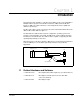
CHAPTER 1 Introduction This manual provides guidelines on the fiber-optic cabling used to connect AutoMax™ Distributed Power System Universal Drive Controllers (UDC) and Power Module Interfaces (PMI). The cable is immune to electromagnetic interference (EMI) and eliminates ground loops. The fiber-optic cable is a part of a point-to-point serial communication link between the UDC module and the PMI. See figure 1.1.
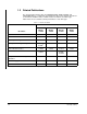
1.2 Related Publications The documentation that describes the SD3000/SF3000, SA500, SA3000, and SA3100 DPS drives is contained in separate binders. Most of the manuals are tailored to describe the hardware and/or software features in detail for each drive type. Table shows the associated document part number for each drive type. Table 1.
1.2.1 1567 Power Max™ Documentation 1567 Power Max medium voltage AC drives also operate under the control of the AutoMax DPS system. The 1567 Power Max binder (S-3040) contains the following manuals: Table 1.
1-4 Fiber-Optic Cabling
CHAPTER 2 Fiber-Optic Cable Assembly Components Fiber-optic cable assemblies are composed of two main components: the connectors and the cable itself. 2.1 Cable The UDC module and the PMI require a 62.5 micron duplex fiber-optic cable. The recommended 62.5 micron fiber-optic cable is Belden cable #225362, Mohawk cable #M92021, or equivalent. This cable has a PVC outer jacket and an internal Kevlar strength member.
2-2 Fiber-Optic Cabling
CHAPTER 3 Fiber-Optic Link Installation The fiber-optic link installation should conform to all applicable codes. ATTENTION: The user is responsible for conforming with all applicable local, national, and international codes. Failure to observe this precaution could result in damage to, or destruction of, the equipment. ! 3.1 Optical Power Budget Fiber-optic communication depends on the launched light signal reaching the receiver at a level high enough to be detected.
The main requirement for reliable fiber-optic link operation is that the total system loss must be less than the power budget. Use the following equations to calculate the losses present in the system: Power Budget Calculation • Cable Loss = Total Cable Length x Cable Attenuation (3.5dB/Km) • Connector Loss = # of Connector Pairs x Connector Attenuation (0.6dB) • Total Loss = Cable Loss + Connector Loss Using the example in figure 3.1: • Cable Loss = 1.1dB Total Cable Length (.
Step 8. Document the fiber-optic cable layout. This document should be maintained for the life of the installation. Step 9. Determine the number of fiber-optic cable components that are needed. Refer to Appendices B, C, and D for more information on recommended components. 3.3 Installation Guidelines The fiber-optic cable must be handled by experienced personnel prior to and during installation. Improper handling may result in damage to the cable.
3.5 Connecting a Fiber-Optic Cable Between a UDC Module and the PMI Use the following procedure to connect a fiber-optic cable (P/N 613613-xxS) between the UDC module and the PMI: Step 1. Remove the dust cover caps from the fiber-optic ports on the UDC module and the PMI. Clean the ports with a can of compressed air. Save the dust caps. All fiber-optic connectors and ports, when not in use, should be covered with dust cover caps. Step 2. Remove the dust cover caps from the fiber-optic cable’s connectors.
UNIVERSAL DRIVE CONTROLLER EM 57652 CARD OK OS OK COMM A OK DRV A FLT COMM B OK DRV B FLT TEST SWITCHES PMI 1 2 3 N.O. METER PORTS 1 2 3 4 COM (ORG.) (BLUE) COMM A P2 XMT PMI (XMT) UDC (XMT) UDC (RCV) PMI (RCV) FIBER-OPTIC CABLE RCV COMM B FIBER-OPTIC WIRE (ORG.) C O M M L I N K XMT P3 RCV (BLUE) XMT RCV Figure 3.2 – Fiber-Optic Cable Assembly Connections .
ST Connector Slot Pins XMT Pin RCV Figure 3.
CHAPTER 4 Fiber-Optic Link Testing and Troubleshooting This chapter describes how to test and troubleshoot the fiber-optic link. 4.1 COMM OK LEDs Under normal operating conditions, i.e., there is an operating system loaded, a UDC module is properly connected to a powered-up PMI, the UDC module’s green COMM OK LED will be on. For the PMI, its COMM OK LED will be turned on when it is properly connected to a powered-up UDC module containing both an operating system and a valid parameter object file.
If the COMM OK LED remains off, remove the test cable and replace the UDC module. If the UDC module’s COMM OK LED lights, turn the loop-back test off by setting bit 15 of registers 101 or 1101 to zero. Then remove the test cable and go to step 3. Step 3. To test the original cable using the UDC module’s fiber-optic transmitter, re-connect the original fiber-optic cable to the UDC module’s ports.
APPENDIX A Fiber-Optic Link Specifications Maximum Distance • 62.5 micron cable: 750 meters (2500 feet) • 50 micron cable: 200 meters (660 feet) Minimum Distance • 62.5 micron cable: 1 meter (3.3 feet) • 50 micron cable: 1 meter (3.3 feet) Optical Power Budget. • 62.5 micron cable: 2.6dB (includes one pair of connectors) • 50 micron cable: 0.
A-2 Fiber-Optic Cabling
APPENDIX B 62.5 Micron Fiber-Optic Cable Specifications Cable Size • 62.5 micron core, 125 micron cladding, 900 micron buffer Recommended Manufacturer • Belden Belden Part Number • 225362 - breakout cable Number of Fibers per Cable • 2 Outside Diameter • 7mm (.275”) Jacket Material • PVC Operating Temperature • -20° to 80°C -36° to 176°F Maximum Pulling Tension • 68 Kg (150 lbs) Minimum Bend Radius • 60 mm (3”) Maximum Attenuation • 3.5 dB per km Nominal Operating Frequency • 820 nanometers 62.
B-2 Fiber-Optic Cabling
APPENDIX C 50 Micron Fiber-Optic Cable Specifications Cable Size • 50 micron core, 125 micron cladding, 900 micron buffer Recommended Manufacturer • Belden Belden Part Number • 227302 - breakout cable Number of Fibers per Cable • 2 Outside Diameter • 5mm (.2”) Jacket Material • PVC Operating Temperature • -20° to 80°C -36° to 176°F Maximum Pulling Tension • 68 Kg (150 lbs) Minimum Bend Radius • 60 mm (3”) Maximum Attenuation • 3.
C-2 Fiber-Optic Cabling
APPENDIX D Fiber-Optic Connector Specifications Recommended Fiber-Optic Connector • Hot Melt Connector, ST-compatible Manufacturer • 3M 3M Part Number • 6100 Ferrule • Ceramic Maximum Attentuation • -0.
D-2 Fiber-Optic Cabling
APPENDIX E Fiber-Optic Cable Assembly Test Set Specifications Recommended Cable Assembly Test Set • Fiber-Optic Test Set, ST-Compatible Manufacturer • 3M/Photodyne 3M/Photodyne Part Number • 118 Recommended Test Cable • Reliance P/N 613613-1S Fiber-Optic Cable Assembly Test Set Specifications E-1
E-2 Fiber-Optic Cabling
DIF Documentation Improvement Form Use this form to give us your comments concerning this publication or to report an error that you have found. For convenience, you may attach copies of the pages with your comments. After you have completed this form, please return it to: Rockwell Automation RGA (Technical Publications) 25001 Tungsten Road Cleveland, Ohio 44117 Fax: 216.266.
Rockwell Automation / 24703 Euclid Avenue / Cleveland, Ohio 44117 / (216) 266-7000 Printed in U.S.A.