
,Startup,Guide User Manual

A-4
Diagnositics, Troubleshooting, and Start-Up Guidelines
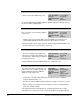
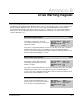
UDC Run Fault Bit 14
The UDC Run Fault bit is set if the UDC task
stops while the minor loop is running in the
PMI Regulator.
Hex Value: 4000H
Sug. Var. Name: FLT_RUN@
Access: Read only
UDC Error Code: 1014
LED: N/A
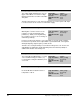
Communication Lost Fault Bit 15
The Communication Lost Fault bit is set if
the fiber-optic communication between the
PMI processor and the UDC module is lost
due to two consecutive errors of any type.
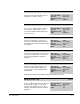
Hex Value: 8000H
Sug. Var. Name: FLT_COM@
Access: Read only
UDC Error Code: 1015
LED: N/A
This bit is set only after communication between the PMI Regulator and UDC
module has been established. This bit should be used in the run permissive logic for
the drive. Also refer to the description of the CCLK Synchronized bit (register
200/1200, bit 14) in S-3056.
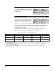
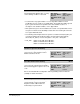
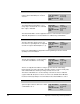
The following table shows how the operation of the digital I/O and Flex I/O is
affected when one or both of the fiber-optic cables is disconnected:
Table A.1 – Effect of a Disconnected Fiber-Optic Cable
Resolver & Drive I/O Analog & Digital
Cable Disconnected MCR AUX OUT Digital Inputs Flex Inputs Flex Outputs
UDC XMT/PMI RCV
Turn Off
1
Update
Last Value
2
Held Reset
3
PMI XMT/UDC RCV
Turn Off
1
Last Value
2
Last Value
2
UDC Control
1. Outputs will remain off until the Fault Reset bit (register 100/1100, bit 8, FLT_RST@) is turned on. At that time, they will be under the
control of the application tasks.
2. The application task(s) in the AutoMax rack must monitor the CCLK Synchronized bit (register 200/1200, bit 14, CCLK_OK@) to
determine if the digital input data is valid.
3. As soon as communication is re-established, outputs become active again; the Warning Reset bit (register 100/1100, bit 9,
WRN_RST@) does not need to be set.