AutoMax™ Distributed Power System Overview Instruction Manual S-3005-3
Throughout this manual, the following notes are used to alert you to safety considerations: ! ATTENTION: Identifies information about practices or circumstances that can lead to personal injury or death, property damage, or economic loss. Important: Identifies information that is critical for successful application and understanding of the product. The thick black bar shown at the margin of this paragraph will be used throughout this manual to indicate new or revised text or figures.
CONTENTS Chapter 1 Introduction 1.1 Distributed Power System (DPS) Manual Organization .................................. 1-1 1.2 1567 Power Max™ Documentation ................................................................. 1-3 1.3 AutoMax Programming Executive Software Manuals ..................................... 1-4 1.4 Standard Engineering Documentation (Instruction Book) ............................... 1-5 Chapter 2 Overview of the AutoMax Distributed Power System 2.1 Software Interface ..........
II AutoMax Distributed Power System Overview
List of Figures Figure 1.1 – Distributed Power System SD3000/SF3000 Drive Manual Map .......... 1-7 Figure 1.2 – Distributed Power System SA500 Drive Manual Map .......................... 1-8 Figure 1.3 – Distributed Power System Medium Power SA3000 Drive Manual Map ................................................................................ 1-9 Figure 1.4 – Distributed Power System High Power SA3000 Drive Manual Map ..............................................................................
IV AutoMax Distributed Power System Overview
List of Tables Table 1.1 – DPS Documentation .............................................................................. 1-3 Table 1.2 – 1567 Power Max Documentation (Binder S-3040) ................................ 1-4 Table 2.1 – Distributed Power Drive Architecture.....................................................
VI AutoMax Distributed Power System Overview
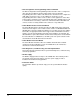
CHAPTER 1 Introduction This manual is intended to provide an introduction to the AutoMax™ Distributed Power System. It begins with a description of how the Distributed Power System (DPS) instruction manuals are organized. It then provides an overview of the hardware components that comprise AC and DC Distributed Power systems and a short introduction to Distributed Power System programming. A glossary of terms used in Distributed Power systems and other AC and DC drive systems can be found in Appendix A.
• Drive Configuration and Programming Instruction Manual The Drive Configuration and Programming manual describes how to configure the drive and Universal Drive Controller (UDC) module using the AutoMax Programming Executive software. This manual also describes how to configure the UDC dual port registers, how to create UDC tasks, and how to use the Programming Executive software on-line for drive control applications.
Table 1.
The 1567 Power Max documentation is listed in table 1.2. Table 1.2 – 1567 Power Max Documentation (Binder S-3040) Document 1.
Binder J2-3092 (AutoMax Programming Reference) contains the following instruction manuals: • J-3675 Enhanced BASIC Language • J-3676 Control Block Language • J2-3093 AutoMax Enhanced Ladder Diagram Editor • J2-3094 AutoMax Enhanced Ladder Language Reference The AutoMax Enhanced BASIC Language manual (J-3675), AutoMax Enhanced Ladder Diagram Editor manual (J2-3093), AutoMax Enhanced Ladder Language Reference manual (J2-3094), and AutoMax Control Block Language manual (J-3676) are contained in the AutoMa
• Interconnection Diagram (W/I) - Diagram showing all interconnecting field wiring between individual assemblies or components provided by Rockwell or others. These diagrams are provided optionally in place of the special cabling instructions in the elementary diagrams (W/E). • Panel Layout Diagram (W/L) - Diagram showing the physical arrangement of the electrical devices on each control panel, including customer connection terminals with wire numbers.
Introduction S-3006 SD3000 Drive Configuration & Programming S-3036 SF3000 Drive Configuration & Programming J-3675 Basic Language J-3676 Control Block Language J2-3093 AutoMax Enhanced Ladder Diagram Editor J2-3094 AutoMax Enhanced Language Reference J2-3102 Programming Executive Other Instruction Manuals S-3005 DPS Overview S-3011 SD3000 Drive Diagnostics, Troubleshooting, and Start-up Guidelines D2-3115 Installing, Operating and Maintaining Engineered Drive Systems AC Line S-3007 Universal Drive Contr
1-8 S-3044 SA500 Drive Configuration & Programming J-3675 Basic Language J-3676 Control Block Language J2-3093 AutoMax Enhanced Ladder Diagram Editor J2-3094 AutoMax Enhanced Language Reference J2-3102 Programming Executive Other Instruction Manuals S-3005 DPS Overview S-3022 SA500 Drive Diagnostics, Troubleshooting and Start-up Guidelines D2-3115 Installing, Operating and Maintaining Engineered Drive Systems AC Line AutoMax Distributed Power System Overview Figure 1.
Introduction DC Bus S-3042 SA3000 Drive Configuration & Programming J-3675 Basic Language J-3676 Control Block Language J2-3093 AutoMax Enhanced Ladder Diagram Editor J2-3094 AutoMax Enhanced Language Reference J2-3102 Programming Executive Figure 1.
1-10 Other Instruction Manuals S-3005 DPS Overview S-3021 SA3000 Drive Diagnostics, Troubleshooting, and Start-Up Guidelines D2-3115 Installing, Operating and Maintaining Engineered Drive Systems D-C Bus J-3650 AutoMax Processor (+) (–) S-3042 SA3000 Drive Configuration & Programming J2-3093 AutoMax Enhanced Ladder Diagram Editor J2-3094 AutoMax Enhanced Language Reference J2-3102 Programming Executive J-3675 Basic Language J-3676 Control Block Language Disconnect AutoMax Rack Fuses AutoMax Distribut
Introduction DC Bus S-3056 SA3100 Drive Configuration & Programming J-3675 Basic Language J-3676 Control Block Language J2-3093 AutoMax Enhanced Ladder Diagram Editor J2-3094 AutoMax Enhanced Language Reference J2-3102 Programming Executive J-3650 AutoMax Processor (+) (–) Disconnect S-3007 Universal Drive Controller Module Other Instruction Manuals S-3005 DPS Overview S-3059 SA3100 Drive Diagnostics Troubleshooting and Start-up Guidelines D2-3115 Installing, Operating And Maintaining Engineered Drive
1-12 Other Instruction Manuals S-3005 DPS Overview S-3502 Power Max™ Installation Guidelines D2-3115 Installing, Operating And Maintaining Engineered Drive Systems S-3050 Power Max™ Drive Configuration & Programming J-3675 Basic Language J-3676 Control Block Language J2-3093 AutoMax Enhanced Ladder Diagram Editor J2-3094 AutoMax Enhanced Language Reference J2-3102 Programming Executive To Supply To Motor Utility Line 3 6 Resolver AutoMax Distributed Power System Overview Figure 1.
CHAPTER 2 Overview of the AutoMax Distributed Power System The AutoMax Distributed Power System is based on a distributed approach to task processing and to control of power conversion for AC and DC drive control.
Modular design ensures upward and downward compatibility of most system components. Retrofits to existing installations are easy to do because UDC modules are compatible with all AutoMax Processors and can even be mixed with existing Reliance drive control modules in the same rack. In most cases, the AutoMax Distributed Power System can be used to upgrade existing drives from other manufacturers. Table 2.
Table 2.1 – Distributed Power Drive Architecture Drive Type AutoMax Software Interface AutoMax Hardware Interface UDC/PMI Communication PMI Type Regulator Type Power Module Voltage Source Neutral Point Clamped 3-Level Inverter 1500 to 5500 HP Motors 8-Slot PMI Rack: 1567 PowerMax Medium Voltage AC Drive AutoMax Programming Executive Software 1. Power Supply 2. PMI Processor Universal 3. Resolver/ Drive Drive I/O Controller Fiber-Optic 4.
2.1 Software Interface All Distributed Power System drive types share a common software interface: the AutoMax Programming Executive. Drive parameter configuration is done via graphical forms (screens) displayed on the programming terminal. The easy-to-use forms display parameters in the appropriate engineering units. The programmer can fill in the blanks and configure the drive using only nameplate data from the motor, the Power Module, current transformer (if used), and resolver or other feedback device.
2.2 DPS Hardware Components Common to All Drive Types There are two hardware components common to all Distributed Power drive systems: the Universal Drive Controller (UDC) module in the AutoMax rack and the fiber-optic link which is used to connect the UDC module to the Power Module Interface (PMI). The PMI/Power Module hardware will vary depending on the drive type. The two sections that follow describe the UDC module and the fiber-optic link in more detail. 2.2.
. UNIVERSAL DRIVE CONTROLLER EM 57652 CARD OK OS OK COMM A OK DRV A FLT COMM B OK DRV B FLT TEST SWITCHES 1 2 3 N.O. METER PORTS 1 2 3 4 COM COMM A XMT RCV COMM B XMT RCV Figure 2.2 – UDC Module Faceplate 2.3 DC Drive Hardware Components For SD3000 and SF3000 DC drives, the PMI is a four-slot rack containing the same Power Supply module, PMI Processor module, and Resolver & Drive I/O module that is used for Medium Power SA3000 AC drives.
PMI PROCESSOR POWER SUPPLY RESOLVER & DRIVE I/O DC POWER TECHNOLOGY OK P1 AUX IN1 RAIL FLT AUX IN2 M E T E R P1 L1 + 1 COM AUX IN3 2 AUX IN4 3 AUX IN5 + COM + COM P O R T S 115 VAC INPUT + COM L2 C O M M 115 VAC INPUT TO FAN L I N K P2 XMT AUX OUT 4 P3 RCV F E E D B A C K R E S O L V E R P4 R A I L 0 P O R T S 1 F W D A R M A T U R E P1 P2 L1 A R M A T U R E MCR EXT FLT P1 F E E D B A C K RPI P.M.
The Power Supply module provides the power necessary for the operation of the modules in the PMI rack. Connections are provided for 115VAC single-phase input power, a ground terminal, and 115VAC output terminals to power a rack fan, if required. Power supply status is indicated by an LED on the faceplate. The RISC-based PMI Processor controls all communication within the PMI rack. It executes the inner control algorithm and provides feedback and diagnostic information to the UDC module.
2.4 AC Drive Hardware Components There are three different types of Power Module Interface hardware configurations depending upon the type of AC Power Modules being used. These configurations are described in the following sections. 2.4.1 SA500 Drives (14-48 Amp) The hardware components of the SA500 drive consist of the DC Bus Supply and the AC Power Module which contains the PMI. These components are shown in figure 1.2 and are described in the following sections.
DC BUS SUPPLY POWER MODULE PWR OK OK COMM OK P.M. FLT EXT FLT RAIL FLT FDBK OK RPI MCR AUX IN1 AUX IN2 AUX IN3 AUX IN4 AUX IN5 AUX OUT RE-BOOT P1 XMT COMM LINK RCV P2 P3 PHASE LOSS RAIL PORT 0 OVER TEMP. DISABLED RAIL PORT 1 PSM READY P4 P5 RESOLVER FEEDBACK P6 TB1 DRIVE I/O POS NEG GND POS NEG GND U V W L1 L2 L3 Figure 2.
T PMI PROCESSOR POWER SUPPLY RESOLVER & DRIVE I/O AC POWER TECHNOLOGY OK OK FDBK OK COMM OK PWR OK AUX IN1 RAIL FLT VW P1 L1 + COM L2 115 VAC INPUT + COM + COM P O R T S + COM L1 L2 115 VAC INPUT TO FAN L I N K 1 AUX IN3 2 AUX IN4 3 AUX IN5 O U T UV IU IW P2 AUX OUT 4 P1 P2 C O M M COM X F E R AUX IN2 M E T E R COM I BC N AB S Y N C H MCR EXT FLT P1 P1 RPI P.M.
The AC Power Technology module performs the calculations required to generate the pulse-width modulated (PWM) signals that fire the power devices in the AC Power Module based on the required feedback inputs and the inner loop reference values received from the UDC module and the PMI Processor. The Power Module Interface port on the faceplate of the AC Power Technology module provides direct connection to the AC Power Module and is used to receive all drive feedback signals and transmit gate driver signals.
POWER SUPPLY PMI PROCESSOR RESOLVER & DRIVE I/O AC POWER TECHNOLOGY AC PARALLEL INTERFACE GATE DRIVER INTERFACE GATE DRIVER INTERFACE GATE DRIVER INTERFACE OK FDBK OK OK OK COMM OK P1 RPI P.M.
The Parallel Interface module (PIM) enables the AC Power Technology module to communicate with up to three Gate Driver Interface (GDI) modules, each connected to a separate power unit. The PIM does the necessary signal splitting and conditioning to make the parallel units behave as if they were a single Power Module. A single connector on the Parallel Interface module faceplate provides the connection to the AC Power Technology module.
2.4.4 SA3100 Drives SA3100 drives are rated from 1 to 800 HP with input voltages from 230 to 575 VAC or from 310 to 775 VDC (common bus). They are supplied in an enclosure for stand-alone operation or open-chassis for mounting within a suitable user-supplied enclosure. Several types of Encoder/Resolver feedback devices are available. An interface for Flex I/O is also provided. The SA3100 drive system is shown in figure 1.5. On SA3100 drives the PMI Regulator is mounted inside the Power Module.
2.4.5 1567 Power Max™ Drive The 1567 Power Max™ drive is made up of two main systems, the Rectifier and the Inverter. Together the Rectifier and Inverter convert fixed frequency, fixed voltage from the AC line to variable frequency, variable voltage power for driving an AC induction motor. The drive is mounted in a lineup of five NEMA 1 general purpose enclosures, housing the rectifier, PMI subsystem and DC/Link, three-phase inverter, AutoMax rack and DC brake, and liquid cooling system.
POWER SUPPLY PMI PROCESSOR MEDIUM VOLTAGE POWER TECHNOLOGY RESOLVER & DRIVE I/O GATE DRIVER INTERFACE GATE DRIVER INTERFACE GATE DRIVER INTERFACE GATE DRIVER INTERFACE OK FDBK OK P1 RPI P.M.
2-18 AutoMax Distributed Power System Overview
CHAPTER 3 Distributed Power System Programming All Distributed Power Drive application programming is done in the AutoMax environment. This means that the programming tools are incorporated into the AutoMax Programming Executive and that the “master” module in the rack is the AutoMax Processor module. Also required is the DPS drive software which contains the operating systems for the Universal Drive Controller modules and the Power Module Interface hardware.
Figure 3.1 shows the AutoMax Executive off-line programming applications. T SYSTEM CONFIGURATOR Manage Tasks Configure Racks or Zoom In RACK CONFIGURATOR Main O I R I O U D C PMI Zoom In Configure Variables Zoom In Remote Head Remote I/O Network Zoom In 0 1 2 3 Remote Configure Variables Zoom In Zoom In O Digital Rail Zoom In or Configure Variables TASK MANAGER Configure Variables Zoom In or Configure Variables VARIABLE CONFIGURATOR Figure 3.
3.2.2 Configuring Racks and Variables Once you have documented the system/section/rack structure of your application via the System Configurator, you can begin to configure the hardware in your installation. Hardware configuration consists of adding modules to each rack (including network and remote racks, UDC modules, PMI rail hardware, and drive parameters) to reflect the actual installation. The AutoMax Executive software checks that modules are added properly.
Figure 3.3 – Configuring Variables After you have completed the physical configuration of your system, you can generate a bill-of-material which lists all of the racks, heads, rails, and modules used in the system along with the needed batteries, cables, and optional hardware and software. 3.2.3 Creating Application Tasks After you have configured I/O points and common memory using variable names, you can create programs, called application tasks in the AutoMax environment.
Ladder Logic Tasks Ladder Logic tasks are created using a custom editor included with the Programming Executive software. These tasks can run on the AutoMax Processor. In addition to the language in which they are written, tasks can also be classified by where they execute. Tasks that run on AutoMax Processors (written in any of the three languages) are called AutoMax tasks.
• Command data This information consists of data stored in the UDC dual port memory. The UDC task or an AutoMax task writes to these registers to enable or disable the control algorithm, to request self-tuning of certain system characteristics, and to specify the reference to the control algorithm. • Pre-defined variables This information consists of the pre-defined variables used to store data such as minor loop gain data, resolver calibration data, and diagnostic data.
APPENDIX A Glossary AC contactor: a contactor designed for the specific purpose of establishing and interrupting an AC power circuit. AC current: current that reverses direction of flow at regular intervals; the measure of the intervals is the frequency (60Hz in US, 50Hz in Europe); available in single phase and three-phase. AC motor: a motor designed to operate on alternating current; there are two primary types, induction and synchronous.
armature resistance: amount of opposition to current flow from the armature circuit. Measured in ohms on a cold motor. armature voltage feedback: signal proportional to armature voltage. Used to regulate Power Module output. attenuation: signal reduction inherent in a transmission line or cable over a given distance. The amount of loss is usually stated in decibels per kilometer at a specific wavelength. back-to-back converter: see anti-parallel.
buffer (fiber-optic communications): the protective coating over an optical fiber. buffer (software): a temporary data storage location. burst (thyristor or gate control): in IEEE usage, a waveform composed of a pulse train. bus: a conductor, or pair of conductors, used as a path over which information or signals are exchanged. cascaded loops: a multiple series of nested control loops. CCLK: the constant clock signal on the AutoMax rack backplane that provides a timing source for modules in the rack.
continuous conduction: the point at which there is an uninterrupted flow of current to the motor. control algorithm: In general, software that regulates a quantity such as voltage, power, speed, etc., at a set value or between certain close limits. Also called regulator. converter: used generally to mean a machine or device for changing AC to DC, or vice versa, or from one frequency to another. See also rectifier. core (fiber-optic cabling): the center of a cable which carries optical signals.
dual port memory: memory accessible to two or more microprocessors. The UDC module has dual port memory that can be accessed by the UDC microprocessor and AutoMax Processors in the rack. duty cycle: a description of the variation of load with time. dv/dt: the change in voltage versus the change in time. dynamic braking: see braking. EMF: electromotive force; voltage or potential difference.
full-wave rectification: rectifying the positive half-cycle of the AC sine wave and the negative half-cycle of the AC sine wave (by inversion) so that the output voltage contains two positive half-sine pulses for each AC input voltage cycle. gain: ratio of output to input. In Distributed Power systems, gain values are held in pre-defined Local Tunable variables. Values can be generated by the PMI via selftuning commands. gate: the control element of a power device.
linearity: a measurement of how closely a ratio (e.g., output/input) follows a straight line. link (fiber-optic): in Distributed Power systems, the fiber-optic cabling which connects a UDC module to a PMI. LOCAL (variable): a variable that is not defined in the rack configuration and is therefore accessible only to the application task in which it is defined. loop: a control scheme in which a reference input to a device is compared to a feedback signal from the device for purpose of regulation.
multimode (fiber-optic cabling): a type of light propagation in which all of the light rays do not travel in parallel with the axis of the fiber. Since the light rays follow different paths in the fiber, their transit times will differ. The difference in transit times results in a specific bandwidth that the multimode fiber can support. nanometer: one-billionth of a meter (10-9). NEC: National Electrical Code; the recommendations of the National Fire Protection Association, revised every three years.
phase sequence reversal: a reversal of the normal phase sequence of the AC power supply. Can be accomplished by the interchange of any two lines on a three-phase system. phase shift: the phase angle difference between two sinusoidal signals of the same frequency. Also, the displacement between corresponding points in similar wave shapes, expressed in degrees lead or lag. phase, single (AC circuits): a circuit energized by a single AC source.
reversing: changing the direction of rotation of the motor armature or rotor. An AC motor is reversed by swapping two of the three motor leads. A DC motor is reversed by changing either the polarity of the voltage applied to the field or the armature, but not both. The reversing function is performed in one of the following ways: contactor reversing changes the polarity of the voltage applied to a DC motor armature with switching contactors.
shunt: usually refers to a calibrated meter shunt that produces a low-voltage signal proportional to the current flow through it. shunt wound: a DC motor or generator in which field excitation is supplied by a winding which may be connected in parallel with the armature, but is normally separately excited. silicon controlled rectifier (SCR): a solid-state switch, sometimes referred to as a thyristor. The SCR has an anode, cathode, and control element called the gate.
UDC task: an application task written in Control Block language that runs on a UDC (Universal Drive Controller) module. This task usually consists of an outer control loop and associated logic. thermal overload relay: an overload relay that functions (trips) in response to the temperature rise in the sensing element caused by excessive current. thyristor: device controlling the current through the Power Module. Synonymous with silicon controlled rectifier in Reliance documentation.
W/N (Note Sheet): installation wiring instructions and definitions of the standard notes and nomenclature used in the drawings. The notes indicate the location of the components or subassemblies that may be separately mounted. W/O (Operator’s Station Diagram): diagram showing the arrangement of the devices on an operator’s station and the location of field terminals with wire numbers. W/P (Program Documentation): block diagrams of application tasks.
A-14 AutoMax Distributed Power System Overview
DIF Documentation Improvement Form Use this form to give us your comments concerning this publication or to report an error that you have found. For convenience, you may attach copies of the pages with your comments. After you have completed this form, please return it to: Rockwell Automation RGA (Technical Publications) 25001 Tungsten Road Cleveland, Ohio 44117 Fax: 216.266.
Printed in U.S.A.