
User guide


II
SA3100 Power Modules
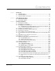
3.16 Commissioning the Drive ...............................................................................3-25
3.16.1 Checking the Installation with Power Off............................................3-26
3.16.2 Checking the Installation with Power On............................................3-26
3.16.2.1 Checking the AC Supply........................................................3-26
3.16.2.2 Checking the DC Bus Supply ................................................3-27
3.16.3 Starting the Drive................................................................................3-27
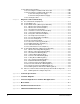
Chapter 4 Diagnostics and Troubleshooting
4.1 Recommended Test Equipment.......................................................................4-1
4.2 System Diagnostics..........................................................................................4-2
4.3 Power Module Faults (UDC Register 202/1202)..............................................4-2
4.3.1 DC Bus Overvoltage Fault (Bit 0) .........................................................4-3
4.3.2 DC Bus Overcurrent Fault (Bit 1) .........................................................4-3
4.3.3 Ground Current Fault (Bit 2).................................................................4-3
4.3.4 Instantaneous Overcurrent Fault (Bit 3) ...............................................4-3
4.3.5 Isolated 12V Supply Fault (Bit 4)..........................................................4-3
4.3.6 Charge Bus Time-Out Fault (Bit 6).......................................................4-3
4.3.7 Overtemperature Fault (Bit 7)...............................................................4-4
4.3.8 Resolver Broken Wire Fault (Bit 8).......................................................4-4
4.3.9 Resolver Fault (Bit 9)............................................................................4-4
4.3.10 Overspeed Fault (Bit 9) ........................................................................4-4
4.3.11 AC Power Technology Fault (Bit 11) ....................................................4-4
4.3.12 PMI Regulator Bus Fault (Bit 13)..........................................................4-4
4.3.13 UDC Run Fault (Bit 14) ........................................................................4-5
4.3.14 Communication Lost Fault (Bit 15) .......................................................4-5
4.4 Power Module Warnings (UDC Register 203/1203) ........................................4-5
4.4.1 DC Bus Overvoltage Warning (Bit 0)....................................................4-5
4.4.2 DC Bus Undervoltage Warning (Bit 1)..................................................4-5
4.4.3 Ground Current Warning (Bit 2) ...........................................................4-5
4.4.4 Voltage Ripple Warning (Bit 3) .............................................................4-5
4.4.5 Reference In Limit Warning (Bit 4) .......................................................4-5
4.4.6 Tuning Aborted Warning (Bit 5)............................................................4-6
4.4.7 Over Temperature Warning (Bit 7) .......................................................4-6
4.4.8 Bad Gain Data Warning (Bit 8).............................................................4-6
4.4.9 Thermistor Open Circuit Warning (Bit 9) ..............................................4-6
4.4.10 Flex I/O Communication Warning (Bit 13)............................................4-6
4.4.11 CCLK Not Synchronized Warning (Bit 14) ...........................................4-6
4.4.12 PMI Regulator Communication Warning (Bit 15)..................................4-6
4.5 Where To Find Information On Replacing Power Module Components ..........4-7
4.5.1 PMI Regulator Assembly Components ................................................4-7
Appendix A Technical Specifications ....................................................................................... A-1
Appendix B Schematic Diagrams.............................................................................................. B-1
Appendix C Inverter Configurations for Common Bus Applications.....................................C-1
Appendix D Motor Cables .......................................................................................................... D-1
Appendix E Gate Driver Board Connections............................................................................ E-1
Appendix F SA3100 Internal DC Bus Control .......................................................................... F-1