Distributed Power System SA3100 AC Power Modules Instruction Manual S-3058-1
Throughout this manual, the following notes are used to alert you to safety considerations: ! ATTENTION: Identifies information about practices or circumstances that can lead to personal injury or death, property damage, or economic loss. Important: Identifies information that is critical for successful application and understanding of the product.
CONTENTS Chapter 1 Introduction 1.1 Standard Features ........................................................................................... 1-3 1.2 Related Publications ........................................................................................ 1-3 1.3 Related Hardware and Software ..................................................................... 1-6 Chapter 2 Power Module Description 2.1 Mechanical Description .......................................................................
3.16 Commissioning the Drive ...............................................................................3-25 3.16.1 Checking the Installation with Power Off ............................................3-26 3.16.2 Checking the Installation with Power On ............................................3-26 3.16.2.1 Checking the AC Supply........................................................3-26 3.16.2.2 Checking the DC Bus Supply ................................................3-27 3.16.
List of Figures Figure 1.1 – SA3100 Catalog Numbering Scheme................................................... 1-1 Figure 3.1 – B Frame and C Frame Dimensions ...................................................... 3-3 Figure 3.2 – D Frame Dimensions............................................................................ 3-4 Figure 3.3 – E Frame Dimensions ............................................................................ 3-5 Figure 3.4 – F Frame Dimensions ....................................
Figure E.1 – Frame Size B Gate Driver Board Connections.................................... E-1 Figure E.2 – Frame Size C Gate Driver Board Connections.................................... E-2 Figure E.3 – Frame Size D Through H Gate Driver Board Connections.................. E-3 Figure F.1 – Internal DC Bus Schematics (B Frame Low Horsepower Power Modules) .............................................................................................. F-1 Figure F.
List of Tables Table 1.1 – Power Module Rating Codes ................................................................. 1-2 Table 1.2 – SA3100 Documentation (Binder S-3053) .............................................. 1-3 Table 1.3 – SA3100 Power Structure Service Manual Cross Reference ................. 1-4 Table 3.1 – Maximum Recommended Input Line Fuse Ratings............................. 3-10 Table 3.2 – TB1 Signals .......................................................................................
VI SA3100 Power Modules
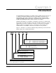
CHAPTER 1 Introduction The SA3100 AC Power Modules are variable-voltage, variable-frequency inverters for use within the AutoMax™ Distributed Power System (DPS) environment. These Power Modules drive 3-phase AC motors at variable speeds using pulse-widthmodulation (PWM) technology. Operation is programmed and controlled using the AutoMax Programming Executive software (Version 3.5 or higher).
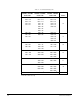
Table 1.1 – Power Module Rating Codes A/Q 230VAC / 310VDC Code = HP B/R 460VAC / 620VDC Code = HP C/W 575VAC / 775VDC Code = HP 001 = 1.0 001 = 1.0 001 = 1.0 003 = 3.0 003 = 3.0 003 = 3.0 007 = 7.5 007 = 7.5 007 = 7.
1.1 Standard Features Distributed Power System SA3100 Power Modules have the following features: • Input power supplied from a three-phase AC line or a common DC bus • PWM inverter to convert DC power to variable frequency AC power for 3-phase induction motors • IGBT power semiconductors • Carrier switching frequencies from 1 to 12 kHz, 1 to 6 kHz, or 1 to 4 kHz, depending upon model (See Appendix A).
Power Module replacement parts and service procedures are contained in the instruction manuals listed in table 1.3. Table 1.3 – SA3100 Power Structure Service Manual Cross Reference AC Input Voltage DC Bus Input Voltage Nominal HP Frame Size Use Service Manual 1336 Force- B 6.11 C 6.12 D 6.13 E 6.14 1 3 7.
Table 1.3 – SA3100 Power Structure Service Manual Cross Reference AC Input Voltage DC Bus Input Voltage Nominal HP Frame Size Use Service Manual 1336 Force- B 6.11 C 6.12 D 6.13 E 6.14 F 6.14 G 6.15 H 6.15 1 3 7.
Table 1.3 – SA3100 Power Structure Service Manual Cross Reference AC Input Voltage DC Bus Input Voltage Nominal HP Frame Size Use Service Manual 1336 Force- B 6.11 C 6.12 D 6.13 E 6.14 F 6.16 G 6.15 H 6.15 1 3 7.5 10 15 20 25 30 40 50 60 500 VAC 600 VAC [C] 675 VDC 800 VDC [W] 75 100 125 150 200 250 300 350 400 450 500 600 650 800 1.
CHAPTER 2 Power Module Description This chapter provides information on the Power Module’s mechanical and electrical characteristics. The individual components of the Power Module differ according to the type of input power (AC or DC) and the Power Module’s horsepower rating and frame size. Appendix B provides a schematic diagram of each design. The following sections provide a general description of the Power Module’s main components and their functions. 2.
Pre-charge Assembly • The pre-charge assembly for common bus and diode rectified stand-alone Power Modules consists of a pre-charge resistor or resistors, SCR/diode, and a printed circuit board assembly. The SCR/diode is used to bypass the pre-charge resistor(s) after bus voltage reaches a programmable threshold value. DC-to-DC Converters • The DC-to-DC converters provide 24 VDC for use by the gate drivers as well as the +5, +15, and -15 VDC necessary for the PMI Regulator and other circuits.
2.2 Electrical Description On AC input Power Modules, three-phase input power is applied through terminals R-L1, S-L2, and T-L3. A current transformer is used to sense ground faults. The AC input voltage is converted into DC voltage by a three-phase full-wave rectifier bridge. See Appendix B. On small (B frame) common bus Power Modules, the negative DC bus is applied to the R-L1 input (TB1-5). The positive DC bus is applied to the T-L3 input (TB1-7). See figure 3.7 and Appendix C.
2-4 SA3100 Power Modules
CHAPTER 3 Installation Guidelines ! ATTENTION: Only qualified electrical personnel familiar with the construction and operation of this equipment and the hazards involved should install, adjust, operate, or service this equipment. Read and understand this manual and other applicable manuals in their entirety before proceeding. Failure to observe this precaution could result in severe bodily injury or loss of life.
3.2 Mounting the Power Module ! ATTENTION:Care must be taken to prevent debris (metal shavings, conduit knockouts, etc.) from falling into the Power Module while performing any installation work on or around the Power Module. Power Modules in enclosures must be mounted in such a way that there is sufficient space at the top, sides, and front of the cabinet to allow for heat dissipation. Allow at least 152.4 mm (6 in) above and below, and 101.6 mm (4 in) on each side between adjacent Power Modules.
A Y D C MAX. Z E B KNOCKOUT LOCATION WILL VARY WITH HP 0.280 0.280 MOUNTING HOLES (4) 0.500 0.500 CONTROL AND SIGNAL WIRING: FIBER-OPTIC, METER PORTS, FLEX I/O, RESOLVER FEEDBACK & DRIVE I/O 115/24V DC FOR PRE-CHARGE ENABLE OR EXTERNAL 24V FOR GATE DRIVE/P.S. BOARD U (T1), V (T2), W (T3) TO MOTOR INPUT POWER: +DC & -DC OR R(L1), S(L2), T(L3) PE (EARTH GROUND) ALL DIMENSIONS IN MILLIMETERS AND (INCHES) ALL WEIGHTS IN KILOGRAMS AND (POUNDS) FRAME REFERENCE A B C MAX. D E Y B1, B2 276.
Y C MAX. D E B INPUT POWER: +DC & -DC, OR R(L1), S(L2),T(L3) PE (EARTH GROUND) & U(T1), V(T2), W(T3) TO MOTOR KNOCKOUTS 10.663 MOUNTING HOLES (4) CONTROL AND SIGNAL WIRING: FIBER-OPTIC, METER PORT, FLEX I/O, RESOLVER FEEDBACK & DRIVE I/O, 115V/24V DC FOR PRE-CHARGE ENABLE OR EXTERNAL 24V FOR GATE DRIVE P.S. BOARD 0.280 0.280 0.500 0.500 ALL DIMENSIONS IN MILLIMETERS AND (INCHES) ALL WEIGHTS IN KILOGRAMS AND (POUNDS) FRAME REFERENCE D A B C MAX. D E 381.5 (15.02) 1240.0 (48.82) 270.8 (10.
C MAX. A Y D Z E B TE, +DC, -DC, AND PE INPUT POWER: R(L1), S(L2), T(L3) U(T1), V(T2), W(T3) TO MOTOR AA MOUNTING HOLES (4) 0.280 CONTROL AND SIGNAL WIRING: FIBER-OPTIC, METER PORT, FLEX I/O, RESOLVER FEEDBACK & DRIVE I/O, 115V/24V DC FOR PRE-CHARGE ENABLE OR EXTERNAL 24V FOR GATE DRIVE P.S. BOARD 0.280 0.500 0.500 ALL DIMENSIONS IN MILLIMETERS AND (INCHES) ALL WEIGHTS IN KILOGRAMS AND (POUNDS) FRAME REFERENCE A B C MAX. D E Y Z AA E-ENCLOSED 510.0 (20.12) 1498.6 (59.00) 424.4 (16.
Figure 3.
$// ',0(16,216 ,1 0,//,0(7(56 $1' ,1&+(6 Figure 3.
3.3 AC Supply Source Requirements SA3100 Power Modules are suitable for use on grounded supply circuits capable of delivering up to a maximum of 200,000 rms symmetrical amperes, 600 volts maximum, when used with the AC input line fuses specified in table 3.1. Conditioning of the AC line may be required for an unbalanced distribution system, or a system with a low impedance relative to the Power Module input.
3.4 Installing a Line Input Disconnect ! ATTENTION: The NEC, CEC, and IEC require that a supply circuit disconnect be provided in the incoming power lines. Failure to observe this precaution could result in severe bodily injury or loss of life. A supply line disconnect must be provided in the incoming power lines in accordance with NEC/CEC guidelines. Size the disconnect according to the in-rush current, as well as any additional loads the disconnect may supply.
. Table 3.1 – Maximum Recommended Input Line Fuse Ratings Drive Catalog No. kW (HP) Rating 200 - 240V Rating 380 - 480V Rating 500 - 600V Rating UL Class CC, T, J1 - BS88 (non-UL installations) SA3100-_001-_ _ 0.75 (1) 10A 6A 6A SA3100-_003-_ _ 2.2 (3) 15A 10A 10A SA3100-_007-_ _ 5.5 (7.5) 40A 20A 15A SA3100-_010-_ _ 7.5 (10) 50A 30A 20A SA3100-_015-_ _ 11 (15) 70A 35A 25A SA3100-_020 -_ _ 15 (20) 100A 45A 35A SA3100-_025 -_ _ 18.
3.7 Power Cabling Using Terminal Block TB1 ATTENTION:The user is responsible for conforming with all applicable local, national, and international codes. Failure to observe this precaution could result in damage to, or destruction of, the equipment. ! Input and output power connections are made through terminal block TB1, located on the Gate Driver board for frame size B (1 to 15 HP, 240V; 1 to 30 HP, 380V, 1 to 20 HP, 600V) Power Modules.
Table 3.2 lists the TB1 signals. Wiring specifications are listed in table 3.3. Table 3.2 – TB1 Signals Terminal Description PE Power Earth Ground R (L1), S (L2), T (L3) AC Line Input Terminals +DC, -DC DC Bus Terminals1 U (T1), V (T2), W (T3) Motor Connection 1. Use terminals R (L1) and T (L3) for common bus connections in a B-frame unit (see Figure 3.7). Table 3.3 – TB1 Wiring Specifications1 Drive Frame Size Max/Min Wire Size2 mm2 (AWG) Maximum Torque N-m (lb-in) B1 8.4/0.8 (8/18) 1.
+DC -DC Common Bus Connection +DC -DC Common Bus Connection Figure 3.
Figure 3.
Figure 3.
Figure 3.10 – Terminal Block TB1 (H Frame Drives) 3.8 Interlocking the Pre-charge Circuit and DC Bus Disconnect for Common Bus Units Pre-charge circuit power on C through H frame common bus units must be interlocked with the bus disconnect. The connection is made to a 3-position terminal block identified as TB1 on the pre-charge printed circuit board. Either AC or DC control power can be used in the precharge circuit.
3.9 Selecting the Proper Lug Kit for Your System D, E, F, G, and H frame Power Modules have stud type terminals and/or bus bars/bolts that require standard crimp-type connectors for cable termination. Connectors such as T & B COLOR-KEYED® Connectors or equivalent are recommended. Table 3.4 lists the lug selection for one possible cable choice. Choose connectors for each installation based on the desired cable sizes, the application requirements, and all applicable national, state, and local codes. Table 3.
Table 3.4 – Lug Selection AC Input R,S,T Output U,V,W, and PE Power Cable (per phase) Module Qty mm2 (AWG) No. T&B Part DC+ DC-1 No.2 Cable (per phase) Qty Number Qty mm2 (AWG) TE T&B Part No.2 Cable (per phase) Qty Number Qty mm2 (AWG) T&B Part No.2 Qty Number C/W075 1 33.6 (2) 8 541423 1 13.3 (6) 2 541353 1 8.4 (8) 1 541313 C/W100 1 53.5 (1.0) 8 541533 1 13.3 (6) 2 541353 1 13.3 (6) 1 541353 C/W125 1 67.4 (2/0) 8 541583 1 26.7 (3) 2 541473 1 13.
Different levels must be run in separate conduit or wire trays. Classes within a level must be run in separate conduit, but may be run in the same wire trays as long as they are grouped and separated. The IEEE levels and classes are identified on the Drive Systems W/E drawings for installation wiring with slash cabling notes.
3.12 Installing an Emergency Stop ! ATTENTION: The user must provide an external, hardwired emergency stop circuit outside of the drive circuitry. This circuit must disable the drive system is case of improper operation. Uncontrolled machine operation may result if this procedure is not followed. Failure to observe this precaution could result in bodily injury. ATTENTION: SA3100 drives are controlled by input signals that start and stop the motor.
If cable trays or large conduits are used to distribute the motor leads for multiple drives, shielded cable is recommended to reduce cross-coupling of noise between the leads of different drives. The shields should be connected to the ground connections at both the motor and drive ends. Armored cable may also provide effective shielding. Ideally, armored cable should be grounded only at the Power Module (PE) and motor frame.
3.14 Grounding the Drive and Motor ATTENTION:The user is responsible for conforming with all local, national, and international codes applicable to the grounding of this equipment. Failure to observe this precaution could result in damage to, or destruction of, the equipment. ! Refer to figure 3.11 for recommended grounding. The Power Module must be connected to the system ground at the power earth (PE) terminal provided on the power terminal block (TB1).
3.14.3 Grounding Discrete Control Wiring The control and signal wiring must be grounded at a single point in the system, remote from the Power Module (i.e., the 0V or ground terminal should be grounded at the equipment end, not at the drive end). If shielded control wires are used, the shield must also be grounded at this point. Refer to the PMI Regulator instruction manual (S-3057) and to the sales order installation requirements for more information about grounding control and signal wiring. 3.14.
3.15 Controlling Power Module Emissions Careful attention must be given to the arrangement of power and ground connections to the Power Module in order to avoid interference with nearby sensitive equipment. The cable to the motor carries switched voltages and should be routed away from sensitive equipment. The ground conductor of the motor cable should be connected to the Power Module ground (PE) terminal directly.
3.15.2 Grounding the RFI Filter ! ATTENTION:RFI filters can only be used with AC supplies that are nominally balanced with respect to ground. In some countries, three-phase supplies are connected in a three-wire configuration with one phase grounded (Grounded Delta). The filter must not be used in Grounded Delta supplies. The optional RFI filter may produce high ground leakage currents.
3.16.1 Checking the Installation with Power Off ! ATTENTION:DC bus capacitors retain hazardous voltages after input power has been disconnected. After disconnecting input power, wait five (5) minutes for the DC bus capacitors to discharge. Then check the voltage across the DC bus to ensure the bus capacitors are discharged before touching any internal components. Failure to observe this precaution could result in severe bodily injury or loss of life.
3.16.2.2Checking the DC Bus Supply Prior to applying power to any Power Module, operation of the DC bus supply should be checked for proper connections, proper operation, correct voltage levels, and correct polarity at termination points. Refer to the appropriate installation and setup instructions for your system’s specific equipment. 3.16.
3-28 SA3100 Power Modules
CHAPTER 4 Diagnostics and Troubleshooting ! ATTENTION:Only qualified electrical personnel familiar with the construction and operation of this equipment and the hazards involved should install, adjust, operate, or service this equipment. Read and understand this manual and other applicable manuals in their entirety before proceeding. Failure to observe this precaution could result in severe bodily injury or loss of life. ATTENTION:Hazard of electric shock exists in this Power Module.
The following equipment should be available before initiating any troubleshooting procedures: • Digital Multimeter (DMM) capable of 1000V DC/750 VAC, with one megohm minimum input impedance. • Clamp on Ammeter (AC/DC) with current ratings to 2X rated current output of SA3100 AC Power Module. • Dual trace oscilloscope with differential capability, digital storage, two X10 and two X100 calibrated probes (for safe high voltage differential measurement).
4.3.1 DC Bus Overvoltage Fault (Bit 0) LED indicator: EXT FLT The DC Bus Overvoltage fault bit is set if the DC bus voltage exceeds the rating of the Power Module. Error code 1018 will be displayed in the error log of the UDC task in which the fault occurred. 4.3.2 DC Bus Overcurrent Fault (Bit 1) LED indicator: P.M. FLT The DC Bus Overcurrent fault bit is set if the DC bus current exceeds 125% of the rated Power Module current.
Error code 1024 will be displayed in the error log of the UDC task in which the fault occurred. If this bit is set, verify that incoming power is at the appropriate level. If the power level is correct, the problem is in the Power Module. 4.3.7 Overtemperature Fault (Bit 7) LED indicator: P.M. FLT The Overtemperature Fault bit is set if the internal temperature of the Power Module’s heatsink exceeds 100° C. Error code 1016 will be displayed in the error log of the UDC task in which the fault occurred. 4.
4.3.13 UDC Run Fault (Bit 14) The UDC Run Fault bit is set if the UDC task stops while the minor loop is running in the PMI Regulator. 4.3.14 Communication Lost Fault (Bit 15) LED indicator: COMM OK The COMM OK LED is turned off, and the Communication Lost Fault bit is set if the fiber-optic communication between the PMI processor and the UDC module is lost due to two consecutive errors of any type. 4.
4.4.6 Tuning Aborted Warning (Bit 5) The Tuning Aborted Warning bit is set if any of the automatic tuning procedures (e.g., resolver balance and gain calibration) is not successful. 4.4.7 Over Temperature Warning (Bit 7) The Over Temperature Warning bit is set if the internal temperature of the Power Module’s heatsink exceeds 90° C. 4.4.8 Bad Gain Data Warning (Bit 8) The Bad Gain Data Warning bit is set if an invalid local tunable variable or drive parameter has been loaded. 4.4.
4.5 Where To Find Information On Replacing Power Module Components ! ATTENTION:Only qualified electrical personnel familiar with the construction and operation of this equipment and the hazards involved should install, adjust, operate, or service this equipment. Read and understand this manual and other applicable manuals in their entirety before proceeding. Failure to observe this precaution could result in severe bodily injury or loss of life.
4-8 SA3100 Power Modules
APPENDIX A Technical Specifications Ambient Conditions • Operating Temperature: Open chassis: 0 to 50° C (32 to 122° F) Enclosed chassis: 0 to 40° C (32 to 104° F). • Storage Temperature: -40 to 70° C (-40 to 158° F). • Relative Humidity: 5 - 95% non-condensing • Altitude: 1000m (3300 ft) without derating • Shock: 15g peak for 11 ms duration (+ 1.0 ms). • Vibration: 0.0006 inches (0.152 mm) displacement. 1G peak.
Programmable Carrier Frequencies Drive HP Rated Carrier Frequency Programmable Carrier Frequency Range 1-3 4 kHz 1-12 kHz 7.5-30 4 kHz 1-12 kHz 40-60 4 kHz 1-12 kHz 75-125 2 kHz 1-6 kHz 150-250 2 kHz 1-6 kHz 300-500 2 kHz 1-4 kHz 600-650 1.5 kHz 1-4 kHz 800 1.5 kHz 1-4 kHz Standard Output Voltage Seven frame sizes (B, C, D, E, F, G, H) are available.
Overload Capability • Continuous: 100% Fundamental current • 1 minute: 150% (B - G frame Power Modules) 135% (H frame Power Modules) Output Frequency Range • Vector Mode: 0 - 400 Hz (limited by feedback devices) • V/Hz Mode: 0 - 600 Hz Output Waveform • Sinusoidal (PWM) Maximum Short Circuit Current Rating • 200,000 A rms symmetrical, 600 volts (when used with AC input line fuses specified in table 3.2). Ride Through • 2 seconds minimum Efficiency • 97.
Input/Output Current Ratings by Model Number The input and output current ratings grouped by drive voltage rating are provided in the following table: Table A.1 – Power Module Input/output Ratings (@ 40° C ambient) Model Nos.
Table A.1 – Power Module Input/output Ratings (@ 40° C ambient) Model Nos.
Enclosure Requirements Table A.2 – Enclosure Requirements Power Module Model No. Base Derate Amps1 Derating Curve2,3 Heat Dissipation Watts2,3 Heatsink Watts2 Total Watts2 230 VAC Output Drives A/Q 001 A/Q 003 A/Q 007 A/Q 010 A/Q 015 A/Q 020 A/Q 025 A/Q 030 A/Q 040 A/Q 050 A/Q 060 A/Q 075 A/Q 100 A/Q 125 4.5 12 27 34 48 65 78 80 120 149 180 240 291 327 None None None Fig A.1 Fig A.2 Fig A.3 Fig A.4 4 Fig A.5 Fig A.6 Fig A.7 Fig A.8 Fig A.
Table A.2 – Enclosure Requirements Power Module Model No. Base Derate Amps1 Derating Curve2,3 Heat Dissipation Watts2,3 Heatsink Watts2 Total Watts2 575 VAC Output Drives C/W C/W C/W C/W C/W C/W C/W C/W C/W C/W C/W C/W C/W C/W C/W C/W C/W C/W C/W C/W C/W C/W C/W C/W W 001 003 007 010 015 020 025 030 040 050 060 075 100 125 150 200 250 3005 3505 4005 4505 5005 6005 6505 800 2.
Derating Guidelines Standard rating for enclosed drive in 40º C ambient and open drive in 50º C ambient. Derating factor for enclosed drive in ambient temperature between 41º C and 50º C. % of Drive Rated Amps 100% – 95% – 90% – 85% – 80% – 75% – 70% – 65% – 1 2 3 4 5 6 7 8 9 10 11 12 9 10 11 12 9 10 11 12 Carrier Frequency in kHz Figure A.
Standard rating for enclosed drive in 40º C ambient and open drive in 50º C ambient. Derating factor for enclosed drive in ambient temperature between 41º C and 50º C. % of Drive Rated Amps 100% – 95% – 90% – 85% – 80% – 75% – 70% – 65% – 60% – 55% – 50% – 45% – 1 2 3 4 5 6 7 8 9 10 11 12 Carrier Frequency in kHz Figure A.
Standard rating for enclosed drive in 40º C ambient and open drive in 50º C ambient. Derating factor for enclosed drive in ambient temperature between 41º C and 50º C. % of Drive Rated Amps 100% – 95% – 90% – 85% – 80% – 75% – 70% – 65% – 60% – 1 2 3 4 5 6 7 8 9 10 11 12 Carrier Frequency in kHz Figure A.7 – Power Module A/Q060 % of Drive Rated Amps 100% – 95% – 90% – 85% – 80% – 75% – 70% – 65% – 1 2 3 4 5 6 Carrier Frequency in kHz Figure A.
Standard rating for enclosed drive in 40º C ambient and open drive in 50º C ambient. Derating factor for enclosed drive in ambient temperature between 41º C and 50º C. % of Drive Rated Amps 100% – 95% – 90% – 85% – 80% – 75% – 70% – 65% – 1 2 3 4 5 6 7 8 9 10 11 12 9 10 11 12 Carrier Frequency in kHz Figure A.10 – Power Modules B/R015 % of Drive Rated Amps 100% – 95% – 90% – 85% – 80% – 75% – 70% – 65% – 60% – 55% – 1 2 3 4 5 6 7 8 Carrier Frequency in kHz Figure A.
Standard rating for enclosed drive in 40º C ambient and open drive in 50º C ambient. Derating factor for enclosed drive in ambient temperature between 41º C and 50º C. % of Drive Rated Amps 100% – 95% – 90% – 85% – 80% – 75% – 70% – 65% – 1 2 4 3 5 6 Carrier Frequency in kHz Figure A.13 – Power Modules B/R100 % of Drive Rated Amps 100% – 95% – 90% – 85% – 80% – 75% – 70% – 65% – 1 2 3 4 5 6 Carrier Frequency in kHz Figure A.
Standard rating for enclosed drive in 40º C ambient and open drive in 50º C ambient. Derating factor for enclosed drive in ambient temperature between 41º C and 50º C. % of Drive Rated Amps 100% – 95% – 90% – 85% – 80% – 75% – 70% – 65% – 60% – 55% – 3 2 1 4 Carrier Frequency in kHz Figure A.16 – Power Module B/R500 % of Drive Rated Amps 100% – 95% – 90% – 85% – 80% – 75% – 70% – 65% – 3 2 1 4 Carrier Frequency in kHz Figure A.
Standard rating for enclosed drive in 40º C ambient and open drive in 50º C ambient. Derating factor for enclosed drive in ambient temperature between 41º C and 50º C. % of Drive Rated Amps 100% – 95% – 90% – 85% – 80% – 75% – 70% – 65% – 60% – 1 2 3 4 5 6 Carrier Frequency in kHz Figure A.19 – Power Modules C/W100 % of Drive Rated Amps 100% – 95% – 90% – 85% – 80% – 75% – 70% – 65% – 60% – 1 2 3 4 5 6 Carrier Frequency in kHz Figure A.
Standard rating for enclosed drive in 40º C ambient and open drive in 50º C ambient. Derating factor for enclosed drive in ambient temperature between 41º C and 50º C. % of Drive Rated Amps 100% – 95% – 90% – 85% – 80% – 75% – 70% – 65% – 60% – 55% – 50% – 45% – 1 2 3 4 5 6 Carrier Frequency in kHz Figure A.22 – Power Module C/W200 % of Drive Rated Amps 100% – 95% – 90% – 85% – 80% – 75% – 70% – 65% – 60% – 55% – 50% – 45% – 40% – 1 2 3 4 5 6 Carrier Frequency in kHz Figure A.
Standard rating for enclosed drive in 40º C ambient and open drive in 50º C ambient. Derating factor for enclosed drive in ambient temperature between 41º C and 50º C. % of Drive Rated Amps 100% – 95% – 90% – 85% – 80% – 75% – 70% – 65% – 1 2 3 4 Carrier Frequency in kHz Figure A.25 – Power Modules C/W450 % of Drive Rated Amps 100% – 95% – 90% – 85% – 80% – 75% – 70% – 65% – 1 2 3 4 Carrier Frequency in kHz Figure A.
Standard rating for enclosed drive in 40º C ambient and open drive in 50º C ambient. Derating factor for enclosed drive in ambient temperature between 41º C and 50º C. % of Drive Rated Amps 100% – 95% – 90% – 85% – 80% – 75% – 70% – 65% – 60% – 55% – 50% – 3 2 1 4 Carrier Frequency in kHz Figure A.28 – Power Modules C/W650 % of Drive Rated Amps 100% – 90% – 80% – 0 1000 (3300) 2000 (6600) 3000 (9900) 4000 m (13,200) (ft) Altitude Figure A.
Required only for the following Power Modules: A/B/C - 025 18.5kW (25 HP) at 8 kHz A/B/C 22kW (30 HP) at 6-8 kHz A/B/C 45 kW (60 HP) at 6 kHz % of Drive Rated Amps 100% – 90% – 80% – 240, 480, or 600V Nominal +2% +4% +6% +8% +10% Input Voltage Figure A.
APPENDIX B Schematic Diagrams The following schematics illustrate the differences in hardware among various drive ratings. These are basic overviews of the SA3100 hardware that should be used as reference material only. See Appendix C for common bus input configurations.
20 -30 HP @ 230 VAC 40 - 60 HP @ 460 VAC 25 - 60 HP @ 575 VAC L1 CONV+ PMC1 DC+ A TB1-3 C1 SCR3 SCR1 R-L1 FT 2/1 R1 2/2 C2 SCR5 R2 R3 2/3 3 FR FS TB1-5 C2 S-L2 TB1-6 T-L3 TB1-7 2 A 1 C4 C5 1/1 R4 1/2 C6 SCR2 SCR6 SCR4 R5 R6 1/3 TB1-4 BC DCCONV- PCB, SNUBBER, E14 E13 E12 E15 STANDARD PRECHARGE BOARD F1 B-2 F2 F3 SA3100 Power Modules
U-M1 E12 CAP PCB V-M2 TB1-8 W-M3 TB1-9 F1 TB1-10 INV+ CAP+ C10 PMI3 PMI2 U C1 CAP BANK C3 B1 C5 B1 B1 E1 E1 B2 E2 Q4 E13 CAP PCB C2 E1 E2 E1 C2 C1 B1 C7 W C1 C1 Q1 A PMI1 V E2 Q6 C2 C1 B1 C8 E2 E2 Q2 C9 C11 E2 -t NTC1 INV- TO CONTROL INTERFAC PCB MOUNT PCB PCB, SNUBBER, 74101-101-XX-ASS’Y.
DC+ 75 & 100 HP @ 230 VAC DC- CUSTOMER FUSING TO BLOWER CIRCUIT U CFI F1 R-L1 AC INPUT POWER 50/60HZ V CF2 W S-L2 CF3 MOV1 T-L3 CM1 CAP BANK PE PE CM2 PE S C N OU NB VB E R A12 S N U B B E R A11 C O N V S N U B B E R A13 +INV C O N V GATE INTERFACE L1 1 C Ck J1 A23 CNV+ PM1 PM2 PM3 K1 K1 K1 G1 G1 G1 SCR1 SCR3 SCR5 (1) (2) DC+ 4 G G1 5 E Ek I S NN VU EB RB TE ER R A20 1 C Ck J1 4 G G1 5 E Ek K2 R20 Q1 GATE INTERFACE A26 K2 GATE INTERFACE Q4 GATE INTERFACE 1 C
CUSTOMER FUSING DC+ TE DC- PE TO BLOWER CIRCUIT CFI F1 R-L1 AC INPUT POWER 50/60HZ 150 - 250 HP @ 380/460V 150 - 300 HP @ 575V U-M1 CF2 S-L2 AC OUTPUT POWER V-M2 CF3 MOV1 T-L3 W-M3 CM1 CAP BANK PE PE PE CM2 PE S CN OU NB VB E R A11 S CN OU NB VB E R A13 S CN OU NB VB E R A12 +INV GATE INTERFACE L1 1 C Ck J1 PM2 PM3 K1 K1 K1 G1 G1 G1 SCR1 R20 A23 CNV+ PM1 SCR3 (1) (2) DC+ Q1 4 G G1 5 E Ek 1 C Ck J1 SCR5 A20 Q4 4 G G1 5 E Ek K2 G2 SCR4 G2 SCR6 1 3 AUXBUS+ GA
DC+ DCCONV SNUBBER CONV SNUBBER CONV SNUBBER A11 A12 A13 L1 CNV+ PM1 TO BLOWER CIRCUIT CUSTOMER FUSING CF1 PM2 DC+ PM3 (1) K1 K1 K1 G1 G1 G1 SCR1 SCR3 SCR5 (2) R-L1 CF2 AC INPUT S-L2 A CF3 T-L3 MOV1 PE K2 K2 K2 G2 G2 G2 SCR4 SCR6 SCR2 PE DC- CNV- (4) (3) STANDARD PRECHARGE BOARD F1 B-6 F2 F3 SA3100 Power Modules
250 - 650 HP PE PE PE U-M1 AC V-M2 OUTPUT W-M3 POWER THS1 R20 R21 R22 R23 R24 R25 INV+ Q11 Q12 C1 B1 C40 J1 1 3 J2 1 3 E1 Q31 Q32 E1 C1 B1 J1 3 J2 1 3 Q52 C1 B1 E1 J1 1 3 J2 1 3 E1 Q42 C1 B1 E1 A21 Q41 CAP BANK C1 B1 E1 A20 A Q51 1 C1 B1 A22 Q61 Q62 Q21 Q22 C1 B1 C1 B1 C1 B1 C1 B1 C1 B1 C1 B1 E1 E1 E1 E1 E1 E1 C41 INV- A23 A24 A25 A27 A26 A28 NTC TO GATE DRIVE TO GATE DRIVE TO GATE DRIVE TO GATE DRIVE TO GATE DRIVE TO GATE DRIVE
DC+ 300 - 400 HP DCTO BLOWER CIRCUIT CFI R-L1 AC INPUT POWER S-L2 50/60HZ U-M1 CF2 AC OUTPUT POWER V-M2 CF3 T-L3 W-M3 PE PE PE CS ON NU VB B E R CS ON NU VB B E R CS ON NU VB B E R A11 A12 A13 +INV GATE INTERFACE 1 C Ck J1 A23 CNV+ PM1 PM2 4 G G1 5 E Ek PM3 K1 K1 K1 G1 G1 G1 SCR3 SCR5 SCR1 G2 SCR4 CNVTB6 AUXBUS+ 1 3 Q1 I S NN VU EB RB TE ER R 1 C Ck J1 4 G G1 5 E Ek K2 R20 GATE INTERFACE CAP BANK A26 K2 GATE INTERFACE A20 Q4 GATE INTERFACE 1 C Ck J1 1 C Ck J1 R2
APPENDIX C Inverter Configurations for Common Bus Applications The figures in this appendix show the inverter configurations of the various SA3100 Power Modules for common bus applications. These figures provide basic overviews of the SA3100 hardware and are to be used as reference material only. Refer to the wiring diagrams (W/Ds), prints, and other documentation supplied with your drive for specific information about your SA3100 common bus drive system.
7.5 - 15 HP @ 230 VAC / 330 VDC 7.5 - 30 HP @ 460 VAC / 650 VDC 7.
Inverter Configurations for Common Bus Applications C-3
20 - 30 HP @ 230 VAC / 330 VDC 40 - 60 HP @ 460 VAC / 650 VDC 25 - 60 HP @ 575 VAC / 820 VDC C-4 SA3100 Power Modules
Inverter Configurations for Common Bus Applications C-5
40 - 60 HP @ 230 VAC / 330 VDC 60 - 150 HP @ 460 VAC / 650 VDC 75 - 125 HP @ 575 VAC / 820 VDC C-6 SA3100 Power Modules
Inverter Configurations for Common Bus Applications C-7
40 - 60 HP @ 230 VAC / 330 VDC 60 - 150 HP @ 460 VAC / 650 VDC 75 - 125 HP @ 575 VAC / 820 VDC C-8 SA3100 Power Modules
Inverter Configurations for Common Bus Applications C-9
150 - 250 HP @ 460 VAC / 650 VDC 150 - 300 HP @ 575 VAC / 820 VDC C-10 SA3100 Power Modules
Inverter Configurations for Common Bus Applications C-11
120 VAC 120V RTN 150 - 250 HP @ 460 VAC / 650 VDC 150 - 300 HP @ 575 VAC / 820 VDC C-12 SA3100 Power Modules
Inverter Configurations for Common Bus Applications C-13
300 - 600 HP @ 460 VAC / 650 VDC 300 - 650 HP @ 575 VAC / 820 VDC C-14 SA3100 Power Modules
Inverter Configurations for Common Bus Applications C-15
300 - 600 HP @ 460 VAC / 650 VDC 300 - 650 HP @ 575 VAC / 820 VDC C-16 SA3100 Power Modules
3 Inverter Configurations for Common Bus Applications C-17
800 HP @ 460 VAC / 650 VDC 800 HP @ 575 VAC / 820 VDC C-18 SA3100 Power Modules
Inverter Configurations for Common Bus Applications C-19
800 HP @ 460 VAC / 650 VDC 800 HP @ 575 VAC / 820 VDC C-20 SA3100 Power Modules
Inverter Configurations for Common Bus Applications C-21
C-22 SA3100 Power Modules
APPENDIX D Motor Cables A variety of cable types are acceptable for SA3100 Power Module installations. For many installations, using separate conductors or unshielded cable is adequate. Signal wire for sensitive circuits must be run in separate conduit and be physically separated from inverter output cables. As an approximate guide, allow a minimum separation of 0.3 meters (1.0 ft) between cable types. Motor cable should be 3-conductor with ground. The motor cables should run in the same wire raceway.
Conduit ! ATTENTION: To avoid possible shock hazard caused by induced voltages, unused wires in the conduit must be grounded at both ends. If a drive sharing a conduit is being serviced or installed, all drives using the same conduit should be disabled to eliminate shock hazard from cross coupled motor leads. If metal conduit is used for cable distribution, observe the following guidelines: • To minimize “cross talk” no more than three sets of motor leads should be routed through a single conduit.
Optional Cable Terminator Voltage doubling at motor terminals, known as reflected wave phenomenon, standing wave, or transmission line effect, can occur when using long motor cables with IGBT PWM Power Modules. Inverter duty motors with phase-to-phase insulation ratings of 1600 volts or higher should be used to minimize effects of reflected wave voltages on motor insulation life.
D-4 SA3100 Power Modules
APPENDIX E Gate Driver Board Connections 50 Main Control Board Interface J1 + BUS 1 - BUS E9 Motor E10 E17 LEM1 E18 E12 E16 E14 J4 E15 E13 E11 LEM2 E27 Bus Switcher Fuse E7 F1 E6 E29 E1 FAN Precharge Resistor E8 E5 E22 E26 E19 E25 E20 E21 10 TB1 1 PE PE DC DC GND GND + - R S T U V W (L1) (L2) (L3) (T1) (T2) (T3) Required Input Fuses To Motor Required Branch Circuit Disconnect AC Input Line +DC -DC Common Bus Connection Figure E.
J2 Ground Fault 50 J1 Main Control Board Interface F3 Bus Discharge Fuse 1 J6 Connection to Lower IGBT’s Current Feedback Interface J7 Main (Bus Volts > Bus Switcher Fuse J8 Connection to Upper IGBT’s F1 TB4 J10 Bus Input Ext 24V Supply Input J9 Standalone or Precharge Board Figure E.
J2 Ground Fault CT Logic Level Supply 50 Main Control Board Interface J1 1 J6 F3 Bus Discharge Fuse Current Feedback Interface J7 Connection to Lower IGBT’s Main Switcher (Bus Volts > 24Vdc) Main Switcher Bus Fuse J8 Connection to Upper IGBT’s TB4 Ext 24V Supply Input F1 J10 Bus Input J9 Standalone or Common Bus Precharge Board Interface Figure E.
E-4 SA3100 Power Modules
APPENDIX F SA3100 Internal DC Bus Control Both AC and DC input SA3100 Power Modules contain a capacitor bank which must be charged before the Power Module can produce current. Because the capacitor bank acts like a DC bus, i.e., it supplies DC power to the inverter section of the Power Module, the capacitor bank is referred to as an “internal” DC bus. An external DC bus, which can be used to supply DC voltage to DC input Power Modules, is provided by the user.
Note that pre-charge circuit power on C frame or larger common bus units must be interlocked with the bus disconnect as shown in figure F.2 below. The connection is made to TB1 (pins 1 and 3) on the pre-charge printed circuit board. Either AC or DC voltage can be used. The selection is determined by the setting of jumper W1. 115 VAC is the default jumper setting.
Note that the bit must be turned on before the programmer enables the bridge test of the inner control loop in the PMI processor in register 100/1100. If BUS_ENA@ is not enabled first, an interlock error will occur (register 205.1205, bit 6, IC_BUS@) and the drive will not be permitted to execute either the bridge test or the control loop.
Idle BUS_ENA@ On* Begin 10 Second Timer No Wait for AC Line Hi HP Common Bus or Hi HP Stand-Alone No ? Yes AC Line Status From Power Module = TRUE No More than 10 Seconds Elapsed? Yes Fault Occurs Register 202/1202 ? Yes Hi HP Stand-Alone ? Yes ** Open Pre-Charge Contactor Wait for Bus to Charge ** Nominal Bus Voltage Reached? No No More than 10 Seconds Elapsed? No More than 10 Seconds Elapsed? Yes Yes ** PMI Closes Pre-Charge Contactor Auxiliary Contacts Closed? ** Yes Open Pr
F.1 Modifying Internal DC Bus Voltage Thresholds The programmer can use three different pre-defined tunable variables to specify three bus voltage thresholds: • OVT_E0% overvoltage threshold • UVT_E0% undervoltage threshold • PLT_E0% power loss threshold These thresholds define the boundaries for specific operating levels. Figure F.4 shows the relative bus voltage operating ranges and how the tunable variables can affect these ranges.
F.2 Internal DC Bus Protection The PMI processor will modify the regeneration or motoring torque limit set by the programmer during parameter entry (calculated from the maximum current and overload ratio parameters) to prevent bus voltage from rising (in the case of regeneration) or falling (in the case of motoring). During regeneration, if bus voltage reaches the overvoltage threshold, the regeneration torque limit will be reduced, and will be set to zero if the overvoltage maximum is reached.
INDEX A AC input, 2-1 AutoMax, 1-1 C Capacitor bank assembly, 2-1 Catalog numbering scheme, 1-1 Common bus inverter configurations, C-1 to C-22 Conduit, 3-21 Controlling emissions, 3-24 to 3-25 isolated 12V supply (bit 4), 4-3 overspeed (bit 9), 4-4 overtemperature (bit 7), 4-4 PMI regulator bus (bit 13), 4-4 resolver (bit 9), 4-4 resolver broken wire (bit 8), 4-4 UDC run (bit 14), 4-5 Fiber-optics communications ports, 2-2 Fuse selection, 3-9 to 3-10 common bus input, C-1 to C-21 fuse ratings, 3-10 G D
mounting the power module, 3-2 to 3-7 planning the installation, 3-1 power cabling, 3-11 to 3-12 selecting lug kits, 3-17 to 3-18 wiring, 3-18 to 3-19 Internal DC bus control, F-1 to F-6 bus control flowchart, F-4 bus protection, F-6 modifying DC bus voltage thresholds, F-5 operating range, F-5 Introduction, 1-1 to 1-6 Inverter power bridge, 2-2 Isolation transformer, 3-8 L Line input disconnect, 3-9 Line reactor, 3-8 Lug kits, 3-17 to 3-18 M Motor cables, D-1 to D-3 cable terminator, D-3 conduit, D-2 lea
reference in limit (bit 4), 4-5 thermistor open circuit (bit 9), 4-6 tuning aborted (bit 5), 4-6 voltage ripple (bit 3), 4-5 Wiring control and signal wiring, 3-19 drive enclosures, 3-19 levels and classes, 3-18 to 3-19 recommendations/practices, 3-19 standard wiring notes, 3-19 Index Index-3
Index-4 SA3100 Power Modules
Rockwell Automation / 24703 Euclid Avenue / Cleveland, Ohio 44117 / (216) 266-7000 Printed in U.S.A.