
Manual
Mechanical/Electrical Description
2-3
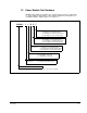
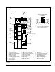
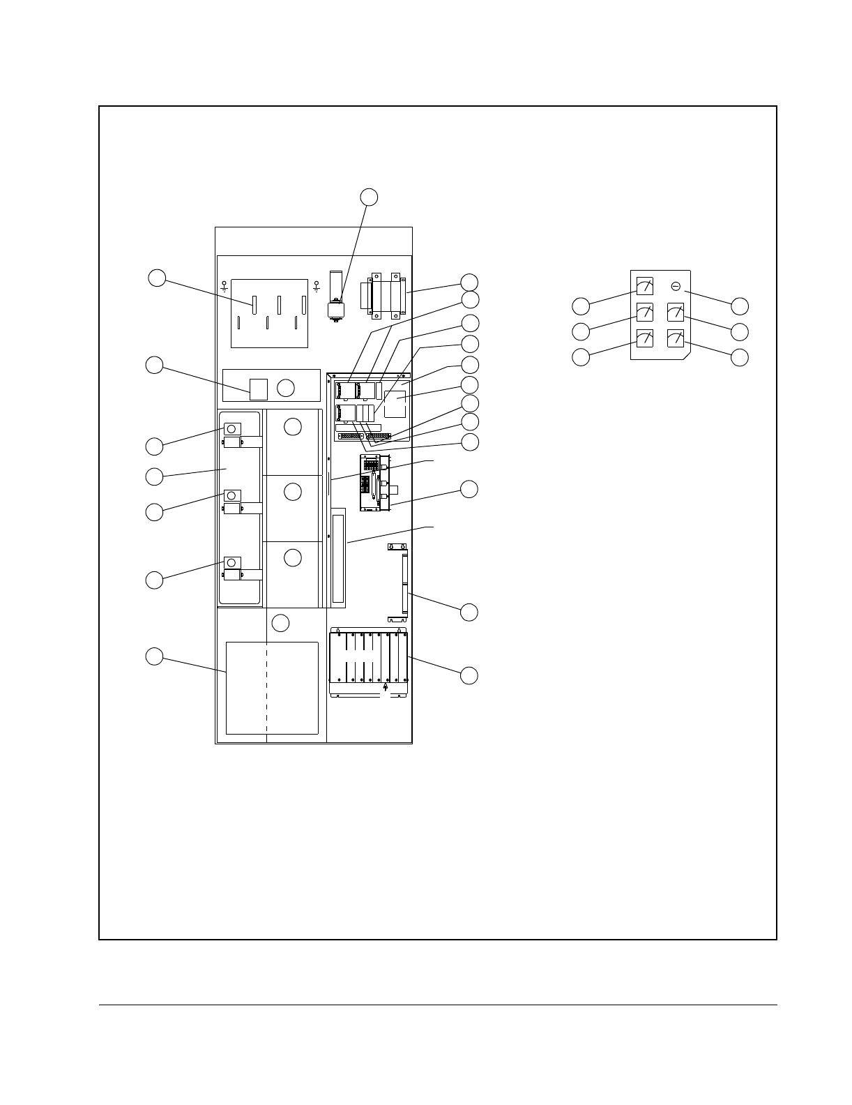
1. Blower Assembly 2. IGBT Phase Module Assembly 3. Capacitor Bank Assembly
4. Pre-charge Assembly
5. DC Disconnect Assembly
1
1. Optional
6. DC bus fuse
7. +/- 15V DC Power Supply 8. 24V DC Power Supplies 9. 115VAC C.B. - Non Critical Pwr
10. Local Power Interface Module 11. 250VA Isolation Transformer 12. Power Module Interface Rack
13. 25KHz Power Supply 14. Reactor Assembly 15. LEM Output Current Sensor
16. Control Fuse (1FU) 17. Control Fuse (3FU) 18. DC Feedback Module
19. 115VAC C.B. - Critical Power 20. Blower Filter 21. Motor Feedback Resistors
22. Power Supply Assembly
23. Door Interlock Bypass Switch
1
24. DC Bus Voltage Meter
1
25. Motor Ammeter
1
26. Motor Voltmeter
1
27. Motor Torque Meter
1
28. Motor Frequency
1
Figure 2.1 – 534A SA3000 Power Module Components
POWER MODULE A
DISCONNECT SWITCH
22
PHASE U
PMI RACK
ASSEMBLY
PHASE W
PHASE V
PRE-CHARGE ASSEMBLY
BANK
AC MOTOR OUTPUT
F
P
M
A
F103
F105
F104
S
L
O
T
6
P
W
R
.
M
O
D
.
A
GDI
U
V
W
CUSTOMER CONTROL WIRING
20
25KHZ PS
12
NAMEPLATE
SALES ORDER
28
23
14
MOTOR
GRD
MOTOR
GRD
5
6
BLOWER
LPI
MODULE
15
15
15
13
3
10
1
2
4
2
2
26
24
CAPACITOR
18
DOOR OF POWER MODULE A.
PANEL IS MOUNTED IN THE CABINET
IF USED, THE OUTPUT METER
25
27
OUTPUT METER PANEL
(OPTIONAL)
C
B
1
±15V
PS
3
F
U
1
F
U
±15V
PS
1
C
B
1
PS
+24V
PS
-24V
PS PS
8
9
19
11
17
16
7