Distributed Power System High Power SA3000 AC Power Modules 850020 – 11xxx, 21xxx (534 Amp) 850020 – 12xxx, 22xxx (972 Amp) 850020 – 13xxx, 23xxx (1457 Amp) Instruction Manual S-3038
Throughout this manual, the following notes are used to alert you to safety considerations: ! ATTENTION: Identifies information about practices or circumstances that can lead to personal injury or death, property damage, or economic loss. Important: Identifies information that is critical for successful application and understanding of the product.
CONTENTS Chapter 1 Introduction 1.1 Standard Features ........................................................................................... 1-1 1.2 Optional Features ............................................................................................ 1-2 1.3 Power Module Part Numbers .......................................................................... 1-3 1.4 Related Publications ........................................................................................ 1-4 1.
Appendix A Technical Specifications........................................................................................... A-1 Appendix B SA3000 Internal DC Bus Control ............................................................................. B-1 Appendix C Replacement Parts................................................................................................... C-1 Index II ..................................................................................................................
List of Figures Figure 1.1 – SA3000 Power Module Part Numbering Scheme ................................ 1-3 Figure 2.1 – 534A SA3000 Power Module Components .......................................... 2-3 Figure 2.2 – 972A 3000A Power Module Components ............................................ 2-4 Figure 2.3 – 1457A SA3000 Power Module Components ........................................ 2-5 Figure 2.4 – Drive I/O and Processor Card Detail .................................................... 2-8 Figure 2.
IV High Power SA3000 AC Power Modules
List of Tables Table 1.1 – SA3000 Power Module Configurations.................................................. 1-1 Table 1.2 – SA3000 Documentation (Binder S-3001) .............................................. 1-4 Table 3.1 – Fuse Ratings.......................................................................................... 3-2 Table 3.2 – Recommended DC Bus Input and AC Output Wire Sizes ..................... 3-2 Table 3.3 – Terminal Tightening Torques..................................................
VI High Power SA3000 AC Power Modules
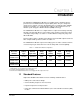
CHAPTER 1 Introduction The High Power SA3000 Power Modules are variable-voltage, variable-frequency power inverters for Distributed Power System (DPS) drives. They are designed to operate from a separate converter (diode bridge, phase-controlled rectifier, SB3000 Synchronous Rectifier, or a common DC bus supply) to drive induction motors at variable speeds using pulse-width modulation (PWM) technology.
• Auto-tuning • Standard cabinet paint 1.
1.3 Power Module Part Numbers SA3000 Power Module part numbers are organized by the number of cabinet bays, i.e., single (534A), double (972A), or triple (1457A) cabinet bay configurations, in combination with the supplied options. See figure 1.1.
1.4 Related Publications This manual describes the hardware components of the SA3000 Inverter Power Module. The other instruction manuals in binder S-3001 describe the SA3000 software, regulator, and communications. Table 1.1 lists the document part numbers. Table 1.
CHAPTER 2 Mechanical/Electrical Description This chapter provides an overview the SA3000 Power Module’s main components and their mechanical and electrical characteristics. 2.1 Mechanical Description The High Power SA3000 Power Modules are variable-voltage, variable-frequency inverters that are housed in protective sheet metal enclosures. The Power Modules are supplied in single, double, and triple bay cabinet configurations, depending upon the current rating. See figures 2.1 to 2.3.
Local Power Interface module (LPI) The LPI module is the interface between the SA3000 Power Module and the PMI rack. It is through this module that information is sent to the SA3000 Power Module and feedback data is sent back to the PMI rack. Capacitor Bank Assembly The capacitor bank's electrolytic capacitors store power locally for the IGBTs.
6 OUTPUT METER PANEL (OPTIONAL) DISCONNECT SWITCH MOTOR GRD MOTOR GRD 5 8 AC MOTOR OUTPUT V U FPMA 14 W 9 24 23 26 25 28 27 19 POWER MODULE A 18 22 PRE-CHARGE ASSEMBLY ±15V PS -24V PS 11 CB1 +24V PS 1FU 3FU 1CB1 4 2 15 3 IF USED, THE OUTPUT METER 16 PANEL IS MOUNTED IN THE CABINET DOOR OF POWER MODULE A.
OUTPUT METER PANEL (OPTIONAL) IF USED, THE OUTPUT METER PANEL IS MOUNTED IN THE CABINET DOOR OF POWER MODULE A.
OUTPUT METER PANEL (OPTIONAL) IF USED, THE OUTPUT METER PANEL IS MOUNTED IN THE CABINET DOOR OF POWER MODULE A.
2.2 Electrical Description DC bus input power is applied to the Power Module through terminals 45 (–) and 47 (+), passes through the optional DC bus disconnect and in-line fuses, and is then fed to the optional pre-charge circuitry. See figures 2.4 to 2.7. When pre-charge circuitry is present and DC input power is applied, the internal DC bus begins charging through the pre-charge resistors.
Each SA3000 Inverter Power Module connected to an SB3000 Power Module supplied DC bus must have a separate pre-charge resistor and contactor to limit the current into its capacitor bank. It is the responsibility of the application tasks to make sure that the SB3000 Power Module is in run before the SA3000 Inverter Power Module is put into run. ! ATTENTION: When used with an SB3000 Power Module, the SB3000 Power Module must be in run before the SA3000 Inverter Power Module is put into run.
FROM 115VAC YYYL YYYN PMI RACK AND OPTIONAL AUTOMATE I/O RAILS ARE MOUNTED IN POWER MODULE FROM T.B.
NOTE: THESE JUMPERS ARE REMOVED WHEN A SEPARATE 115 VAC SUPPLY IS USED FOR THE PMI RACK. CONDITIONED POWER FROM CRITICAL 115VAC SUPPLY DISTRIBUTION 115VAC FROM A-C DISTRIBUTION 800VDC FROM SB3000 GRD D1 D2 INTERLOCK BYPASS S.R. 1CB1 CB1 DC BUS DISCONNECT (OPTIONAL) 0-1000 VDC SA3000 INVERTER W/D 30395-11 D3 DOOR SOLENOID (OPTIONAL) (OPTIONAL) 1FU 5.0A 3FU 3.
NOTE: THESE JUMPERS ARE REMOVED WHEN A SEPARATE 115 VAC SUPPLY IS USED FOR THE PMI RACK. CONDITIONED POWER FROM CRITICAL 115VAC SUPPLY DISTRIBUTION 115VAC FROM A-C DISTRIBUTION 800VDC FROM SB3000 45 GRD D1 D2 INTERLOCK BYPASS SA3000 INVERTER W/D 30395-12 D3 S.R. 1CB1 CB1 25A 25A DC BUS DISCONNECT (OPTIONAL) 0-1000 VDC DOOR SOLENOID (OPTIONAL) (OPTIONAL) 1FU 5.0A 3FU 3.
NOTE: THESE JUMPERS ARE REMOVED WHEN A SEPARATE 115 VAC SUPPLY IS USED FOR THE PMI RACK. CONDITIONED POWER FROM CRITICAL 115VAC SUPPLY DISTRIBUTION 115VAC FROM A-C DISTRIBUTION 800VDC FROM SB3000 ON SHEET YYY (-) 45 GRD D1 (RED) (+) 47 WWWD2 GRD (RED) 1L2 WWWD1 1L1 YYGRD XXX1L2 GRD YYY45 XXX1L1 L2 YYY47 XXX1L1A L1 1L1A WWWIVL2 WWWIVL1 XXXL1A L1A FROM 115VAC D2 INTERLOCK BYPASS SA3000 INVERTER W/D 30395-13 D3 S.R.
2-12 High Power SA3000 AC Power Modules
CHAPTER 3 Installation Guidelines This chapter describes the guidelines and wiring recommendations to be followed when installing High Power SA3000 Power Modules. Installation and replacement procedures are included for the 534A, 972A, and 1457A Power Modules. ! 3.1 ATTENTION: The user is responsible for conforming with all applicable local, national, and international codes. Failure to observe this precaution could result in damage to, or destruction of, the equipment.
3.2 Wiring ATTENTION: The user is responsible for conforming with all applicable local, national, and international codes. Failure to observe this precaution could result in damage to, or destruction of, the equipment. ! System wiring is to be done according to the supplied wiring diagrams (W/Es), which are application-specific. Sections 3.2.1 through 3.2.3 provide additional information on fuses and recommended wiring. 3.2.
Table 3.3 – Terminal Tightening Torques Terminals Tightening Torque DC Bus Input Power: 45, 47 41 Nm (30 lb-ft) Output Power: U, V, W 41 Nm (30 lb-ft) 115 VAC Input Power: L1, L2 3.5 Nm (2.6 lb-ft) 3.2.3 Wire Routing Ac output wiring is routed through the top of the cabinet, above terminals 181, 182 and 183. DC input wiring is also routed through the top of the cabinet.
* Figure 3.1 – 534A Power Module Mounting Dimensions (Single-Bay) 3-4 High Power SA3000 AC Power Modules 1.37 (34.8) (2203.5) 86.75 77.38 (1965.5) 4.00 (101.6) 5.38 (136.7) * ADDITIONAL HEIGHT: COMMON DC BUS ENCLOSURE INSTALLED - 10.00 (254.0). - 19.00 (482.6). DC TOP HAT ENCLOSURE INSTALLED WEIGHT = 1265 LBS (573 KG) ALL DIMENSIONS ARE IN INCHES (MILLIMETERS) 23.75 (603.3) 22.38 (568.5) MTG STUD - MIN LENGTH 1.50 (38.1) .50 D (12.7) DRIP SHIELD AVAILABLE CONDUIT ENTRY AREA IN HOOD.
* Figure 3.2 – 972A Power Module Mounting Dimensions (Double-Bay) Installation Guidelines 3-5 1.37 (34.8) 77.37 (1965.5) 4.00 (101.6) 86.75 (2203.5) (136.7) * WEIGHT = 2175 LBS (985 KG) ALL DIMENSIONS ARE IN INCHES (MILLIMETERS) 64.00 (1625.6) FILTER & FAN 25.00 (635.0) ADDITIONAL HEIGHT: COMMON DC BUS ENCLOSURE INSTALLED - 10.00 (254.0). - 19.00 (482.6). DC TOP HAT ENCLOSURE INSTALLED 23.75 (603.3) 22.38 (568.5) .50 D (12.7) MTG STUD - MIN LENGHT 1.50 (38.1) DRIP SHIELD 5.
Figure 3.3 – 1457A Power Module Mounting Dimensions (Triple-Bay) 3-6 High Power SA3000 AC Power Modules DC TOP HAT ENCLOSURE INSTALLED 4.00 (101.6) 86.75 (2203.5) 77.37 (1965.5) * 94.00 (2387.6) 25.00 (635.0) - 19.00 (482.6). 5.00 (127.0) 25.00 (635.0) WEIGHT = 3085 LBS (1398 KG) ALL DIMENSIONS ARE IN INCHES (MILLIMETERS) ∗ ADDITIONAL HEIGHT: COMMON DC BUS ENCLOSURE INSTALLED - 10.00 (254.0). 23.75 (603.3) 22.38 (568.5) 1.37 (34.8) .50 D (12.7) MTG STUD - MIN LENGHT 1.50 (38.
DC BUS INPUT VOLTAGE 775V GND 115 VAC INPUT VOLTAGE 45 47 L N 115 VAC QUICK CONNECT BLOCK MANUAL DISCONNECT SA3000 POWER MODULE FUSE – + GND U V W OUTPUT CONTACTOR (OPTIONAL) MOTOR Figure 3.
3-8 High Power SA3000 AC Power Modules
CHAPTER 4 Diagnostics and Troubleshooting This chapter describes the equipment needed to check the operation of the Power Module and the tests to be performed. Included are descriptions of the Power Module faults and warnings monitored by the Distributed Power System software. Procedures are also provided for replacing Power Module cabinets, sub-assemblies, and fuses. ! ATTENTION: DC bus capacitors retain hazardous voltages after input power has been disconnected.
4.2 Power Module Tests with Input Power Off Use the following procedure to perform the SA3000 Power Module tests: Step 1. Turn off and lock out DC input power. Step 2. Wait ten minutes to allow the DC bus voltage to dissipate. ! ATTENTION: DC bus capacitors retain hazardous voltages after input power has been disconnected. After disconnecting input power, wait ten (10) minutes for the DC bus capacitors to discharge.
Figure 4.
Table 4.1 – DC Bus and Terminal Tests1 Meter Connections + DC Bus Bus Capacitors Output Terminals Scale - Bus (45) + Bus (47) + Bus (47) - Bus (45) + 349 A,B,C - 349 A,B,C U + V + W + + U + V + W U V U W V W X10 X10 Expected Test Results Capacitor Effect (0 to 50 ohms) Capacitor Effect (0 to 200 ohms) Capacitor Effect (0 to 500 ohms) X1 2 ohms X10 Capacitor Effect (0 to 2k ohms) X1000 4k to 6k ohms 1. With the motor disconnected Table 4.
4.3.1 Power Module Faults The Power Module faults listed in table 4.3 will cause the SA3000 Power Module to shut down. In a fault situation, the PMI Processor will command zero current and will stop firing the Power Module’s IGBTs. Faults must be reset before the SA3000 Power Module can be restarted. Table 4.
4.3.1.4 Instantaneous Overcurrent Fault The Instantaneous Overcurrent Fault bit (bit 3) is set in the Fault register (202/1202) if an overcurrent is detected in one of the power devices (IGBTs). Register 204/1204, bits 0-5, indicates which power device experienced the overcurrent. When 972A and 1457A SA3000 Power Modules are being used, registers 220/1220 and 221/1221 indicate the status of the B and C Power Modules.
4.3.2 Power Module Warnings The following warnings indicate conditions which are not serious enough to shut down the SA3000 Power Module but may affect its performance. See table 4.4. Warnings cause no action by themselves. Any response to a warning condition is the responsibility of the application task. Table 4.
4.3.2.5 Overtemperature Warning The Overtemperature Warning bit (bit 7) is set in the Warning register (203/1203) if the warning level thermal switch (78o C (172.4o F)) in the SA3000 Power Module opens. Bit 12 in register 204/1204, 220/1220, or 221/1221 will be set to indicate which SA3000 Power Module caused the warning. 4.4 Replacing Power Module Fuses and Sub-Assemblies Follow the procedures given in sections 4.4.1 to 4.4.5 to replace the SA3000 Power Module’s fuses and sub-assemblies. 4.4.
Table 4.5 – Power Module Replacement Fuse Specifications Fuse Volts Class Type Rating Rockwell Part Number Torque Specifications 1FU 600 CC KLDR 5A 64676-29R -- 3FU 600 CC KLDR 3.2 A 64676-29P -- FPM A,B,C 1000 Semiconductor 1000 A 64676-80P 41 Nm (30 lb-ft) F103 A,B,C 1000 Semiconductor 630 A 64676-79AZ 20.5 Nm (15 lb-ft) F104 A,B,C 1000 Semiconductor 630 A 64676-79AZ 20.5 Nm (15 lb-ft) F105 A,B,C 1000 Semiconductor 630 A 64676-79AZ 20.
DISCONNECT SWITCH MOTOR GND MOTOR GND U V W FPMA AC MOTOR OUTPUT F101A F102A (FRONT) (REAR) POWER MODULE A (2) +24V. PS -24V. PS CB1 PRE-CHARGE ASSEMBLY 1FU 3FU 1CB1 (3) ±15V. PS 3FU PHASE U (1) BANK F103A 1FU (4) 11FU, 12FU (4) 21FU-26FU 25KHZ PS PHASE W LPI MODULE F104A CAPACITOR PHASE V LINE SYNC PCB F105A SLOT 6 PMI RACK PWR. MOD. A GDI BLOWER ASSEMBLY Notes 1,2,3. See table 4.5 and figure 4.5 Note 4. See table 4.5 and figure 4.6. Figure 4.
DISCONNECT SWITCH MOTOR GRD MOTOR GRD MOTOR GRD V FPMA U FPMB AC MOTOR OUTPUT W F101A F101B (FRONT) F102A F102B (REAR) POWER MODULE B POWER MODULE A (2) +24V PS -24V PS CB1 PRE-CHARGE ASSEMBLY PRE-CHARGE ASSEMBLY PHASE U BANK (4) 11FU, 12FU (4) 21FU-26FU PHASE V BLOWER ASSEMBLY BLOWER ASSEMBLY LPI MODULE GDI GDI PMI RACK PWR. MOD. A F105A LINE SYNC PCB PWR. MOD.
Figure 4.4 – 1457A SA3000 Power Module Fuse Locations BLOWER ASSEMBLY PHASE W PHASE V PHASE U F105B F104B F103B Notes 1,2,3. See table 4.5 and figure 4.5 Note 4. See table 4.5 and figure 4.6.
850100-3R ASSEMBLY (1) OUT+ 1.8A F 0 -15 (1) OUT- CB1 ±15V PS +15 0 3FU N 1FU L1 L1 L2 L1A 1.8A F (2) IN 2.5A T 115 VAC INPUT TERMINAL BOARD 2.5A T L1 L1 N N +24V PS 24 0 (3) OUT -24V PS 24 0 2.0A F 2.0A F 1QD 2QD NON-CRITICAL (FAN) 115VAC CRITICAL (PMI/PS) 115VAC 850100-3S ASSEMBLY 2.5A T 2.5A T L1 L1 N +24V PS 24 0 (3) OUT 2.0A F N -24V PS 24 0 CB1 (2) IN 2.0A F L1 1.8A F ±15V PS (1) OUT- 0 -15 3FU N +15 0 1CB1 L1 1FU (1) OUT+ 1.
Figure 4.6 – 25 KHz. Power Supply - 288 289 FRONT VIEW 2FU Note 4. See table 4.5 for fuse specifications. (4) 11FU 12FU(4) + NOT 115VAC USED INPUT 1FU 4-14 High Power SA3000 AC Power Modules 26FU THRU 21FU (4) 802268-16R ASSEMBLY 5 4 3 2 B A 1 TO POWER MODULE(S) C 25 KHz.
4.4.2 Replacing an IGBT Phase Module Assembly Important: When replacing an IGBT phase module assembly be sure to re-install, position, and tighten the hardware in the proper sequence. The IGBT phase module must be aligned correctly to prevent damage to the components. If all three IGBT phase modules are to be replaced, it will be easier to remove them by starting at the top and working down, i.e., begin by removing module U, continue with module V, and then finish by removing module W.
Step 11. Start and finger-tighten the two M6 hex nuts on the negative bus bar. See figure 4.7, callout 4. Step 12. Start and finger-tighten the two 5/16” cap screws, flat washers, and lock washers on the heatsink. One cap screw is located on each side of the heatsink. See figure 4.7, callout 5. Step 13. Start and finger-tighten the two M8 bolts on the AC bus bar. See figure 4.7, callout 3. Tighten the bolts evenly. Step 14. Loosen the M8 bolt on the left side of the fuse. See figure 4.7, callout 1.
PHASE V 3 PHASE W 2 5 4 1 Figure 4.7 – IGBT Module Assembly Mounting Bolt Locations 4.4.2.1 Replacing an IGBT If an IGBT needs to be replaced, it is recommended that the IGBT module be returned to an authorized Rockwell repair facility. 4.4.3 Replacing the Pre-charge Assembly Use the following procedure to replace the optional pre-charge assembly: Step 1. Turn off and lock out DC input power. Step 2. Wait ten minutes to allow the DC bus voltage to dissipate.
Step 3. Open the Power Module cabinet's doors and measure the DC bus potential across each pair of DC bus bars, 347 A,B,C (+ bus) and 345 A,B,C (- bus), with an external voltmeter before working on the unit. See figure 4.1. Step 4. Remove the bracket that is fastened across the cabinet in front of the pre-charge assembly. The bracket is attached to the cabinet with two screws. Step 5. Remove the two power cables marked with a red band from the pre-charge assembly. Step 6.
Step 7. Install the new blower assembly by performing steps 1 through 6 in reverse order. Step 8. Close the cabinet doors and reapply power to the SA3000 Power Module. 4.4.4.1 Replacing a Blower Filter To replace a blower filter: Step 1. Remove the old filter by sliding it out. Step 2. Slide the new filter in. 4.4.5 Replacing a Bus Capacitor Assembly Use the following procedure to replace a DC bus capacitor assembly: Step 1. Turn off and lock out the AC input power. Step 2.
Step 13. Install the new capacitor bank assembly by performing steps 1 through 12 in reverse order. Step 14. Close the cabinet doors and reapply power to the SA3000 Power Module. 4.5 Replacing the Power Module Cabinet Use the following procedure to replace the SA3000 Power Module cabinet: Step 1. Turn off and lock out the AC input power to the DC bus supply control cabinet. Step 2. Wait ten minutes to allow the DC bus voltage to dissipate.
APPENDIX A Technical Specifications Ambient Conditions • Operating Temperature:0 to +40o C (32 to +104o F) • Storage Temperature:-25 to +55o C (-13 to +131o F) • Humidity: 5 to 95%, non-condensing. • Altitude: Do not install above 1000 meters (3300 feet) without derating output current. For every 91.4 meters (300 feet) above 1000 meters (3300 feet), derate the output current by 1%. • Vibration: Sine Wave: 1g., 10-500 Hz., all 3 axes. Shock: 15g., over 6 msec., half sine wave.
DC Bus Specifications • Pre-charge Time: 1 second • Discharge time (below 50V): less than 5 minutes • Pre-charge resistance/bus capacitance: 534A Unit: 7.6 Ω / 32.4 µF 972A Unit: 3.8 Ω / 64.8 µF 1457A Unit: 2.5 Ω / 97.
Output Power • Output Voltage: 575 VAC, maximum • Modulation: Sine Wave, Pulse Width Modulation (PWM) • Short Circuit Rating: 65 KA • Power Dissipation: 534A Unit: 7500 W 972A Unit: 15000 W 1457A Unit: 22500 W • Output Inductor: 7.
A-4 High Power SA3000 Power Modules
APPENDIX B SA3000 Internal DC Bus Control Each DC input High Power SA3000 Power Module contains a capacitor bank which must be charged before the Power Module can produce current. Because the capacitor bank acts like a DC bus, i.e., it supplies DC power to the inverter section of the Power Module, the capacitor bank is referred to as an “internal” DC bus. An external DC bus, which can be used to supply DC voltage to the Power Module, is provided by the user.
The programmer initiates control of the charging process by setting the BUS_ENA@ bit (register 100/100, bit 4). Normally, the PMI processor waits for the rising edge of this bit to start the process. However, if this bit is ON at power-up, the PMI processor will interpret this as a positive transition. The DC bus controller, though, will inhibit the system’s state machine until valid configuration and gain data is received.
Idle (1) BUS_ENA@ On Begin 10 Second Timer (2) Open Pre-Charge Contactor (2) Wait for Bus to Charge Nominal Bus Voltage Reached? No No More than 10 Seconds Elapsed? Yes Fault Occurs Register 202/1202 No More than 10 Seconds Elapsed? Yes Open Pre-Charge Contactor Yes (2) PMI Closes Pre-Charge Contactor (2) Auxiliary Contacts Closed? Yes (2) (2) Yes PMI Sets BUS_RDY@ Fault Bus Charged Occurs? No 1. BUS_ENA@ must transistion from off to on to start the bus charging process. 2.
B.1 Modifying Internal DC Bus Voltage Thresholds The programmer can use three different pre-defined tunable variables to specify three bus voltage thresholds: • OVT_E0% overvoltage threshold • UVT_E0% undervoltage threshold • PLT_E0% power loss threshold These thresholds define the boundaries for specific operating levels. Figure B.3 shows the relative bus voltage operating ranges and how the tunable variables can affect these ranges.
B.2 Internal DC Bus Protection The PMI Processor will modify the regeneration or motoring torque limit set by the programmer during parameter entry (calculated from the maximum current and overload ratio parameters) to prevent bus voltage from rising (in the case of regeneration) or falling (in the case of motoring). During regeneration, if bus voltage reaches the overvoltage threshold, the regeneration torque limit will be reduced, and will be set to zero if the overvoltage maximum is reached.
B-6 High Power SA3000 Power Modules
APPENDIX C Replacement Parts 534 Amp SA3000 Power Module Table C.
534 Amp SA3000 Power Module (Continued) Table C.4 – Pre-charge Assembly (850022-3) Quantity Rockwell Part Number 10 63481-6V Contactor (230A, 600 VAC) 1 705310-39BX Pre-charge Module 1 0-55350-4 Pre-charge Capacitor (4700µH, 50 VDC) 1 600442-31TS Pre-charge Resistors (3.819Ω) 2 48627-G Voltage Feedback Module 1 O-55350-10 Part Description 'LVFKDUJH 5HVLVWRUV .Ω : Table C.
972 Amp SA3000 Power Module Table C.
972 Amp SA3000 Power Module (Continued) Table C.11 – Pre-charge Assembly (850022-3_) Quantity Rockwell Part Number 10 63481-6V Contactor (230A, 600 VAC) 1 705310-39BX Pre-charge Module 1 0-55350-4 Pre-charge Capacitor (4700µH, 50 VDC) 1 600442-31TS Pre-charge Resistors (3.819Ω) 2 48627-G Voltage Feedback Module 1 O-55350-10 Part Description 'LVFKDUJH 5HVLVWRUV .Ω : Table C.
1457 Amp SA3000 Power Module Table C.
1457 Amp SA3000 Power Module (Continued) Table C.18 – Pre-charge Assembly (850022-3_) Quantity Rockwell Part Number 10 63481-6V Contactor (230A, 600 VAC) 1 705310-39BX Pre-charge Module 1 0-55350-4 Pre-charge Capacitor (4700µH, 50 VDC) 1 600442-31TS Pre-charge Resistors (3.819Ω) 2 48627-G Voltage Feedback Module 1 O-55350-10 Part Description 'LVFKDUJH 5HVLVWRUV .Ω : Table C.
INDEX C F Cabinet installation, 3-3 to 3-7 double-bay cabinet (972A unit), 3-5 power and ground connections, 3-7 single-bay cabinet (534A unit), 3-4 triple-bay cabinet (1457A unit), 3-6 Cabinet replacement, 4-20 Capacitor bank assembly, 2-2 Circuitry 1457A power module, 2-11 534A power module, 2-9 972A power module, 2-10 Components, 2-1 to 2-5 1457A power module, 2-5 534A power module, 2-3 972A power module, 2-4 Configurations, 1-1 Control power, 4-13 Fault register 202/1202, 4-5 Faults, 4-5 to 4-6 charg
M Main disconnect, 2-2 Mechanical description, 2-1 to 2-5 1457A power module components, 2-5 534A power module components, 2-3 972A power module components, 2-4 Mechanical/electrical description, 2-1 to 2-11 Mounting dimensions 1335A triple-bay power module, 3-6 534A single-bay power module, 3-4 972A double-bay power module, 3-5 O Optional features, 1-2 Output meters, 2-2 P Part numbers, 1-3 Phase modules description, 2-1 mounting bolt locations, 4-17 Power and ground connections, 3-7 Power supply 115VAC
DIF Documentation Improvement Form Use this form to give us your comments concerning this publication or to report an error that you have found. For convenience, you may attach copies of the pages with your comments. After you have completed this form, please return it to: Rockwell Automation RGA (Technical Publications) 25001 Tungsten Road Cleveland, Ohio 44117 Fax: 216.266.
Rockwell Automation / 24703 Euclid Avenue / Cleveland, Ohio 44117 / (216) 266-7000 Printed in U.S.A.