
Designer Instruction Manual

Publication LOGIX-UM004A-EN-P - March 2007
100 FuzzyDesigner Projects
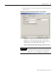
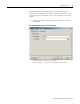
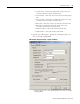
• Equation Format – Specify the equation format of the
controller.
• Derivative Input – Specify the derivative input of the
controller.
• Sampling Period – Specify the sampling period of the
controller. The period must be greater then zero and is the
same for all PIDs applied in the same project.
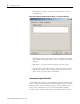
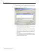
• Parameter b – Select the value of the parameter b entering
the term of the PIDC equation. The value
of the parameter ranges from 0 to 1.
• Dead Band – Click the check box to activate the dead
band of the controller and specify the dead band radius
and dead band type.
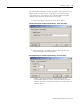
• Dead Band Radius – If the Dead Band check box is
checked, enter the dead band radius of the controller. This
value must be greater then zero.
• Dead Band Type – If the Dead Band check box is
checked, enter the dead band type of the controller.
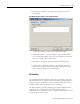
• Output Limiting with AntiReset WindUp – Click the check
box to enable this function, and specify the upper and
lower limits.
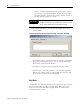
• Minimum – When the Output Limiting check box is
checked, enter the lower saturation limit of the controller
output.
• Maximum – When the Output Limiting check box is
checked, enter the upper saturation limit of the controller
output.
IMPORTANT
The minimum value must be always lower then the maximum
value.
()
PbSPPV∗∗ −