RSLogix 5000 Fuzzy Designer User Manual
Important User Information Solid state equipment has operational characteristics differing from those of electromechanical equipment. Safety Guidelines for the Application, Installation and Maintenance of Solid State Controls (publication SGI-1.1 available from your local Rockwell Automation sales office or online at http://literature.rockwellautomation.com) describes some important differences between solid state equipment and hard-wired electromechanical devices.
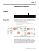
Table of Contents Preface About This Publication. . . . . . . . . . . . . . . . . . . . . . . . . . . . . 7 Who Should Use This Publication. . . . . . . . . . . . . . . . . . . . . 7 Conventions . . . . . . . . . . . . . . . . . . . . . . . . . . . . . . . . . . . . 7 Chapter 1 Get Started with FuzzyDesigner Introduction . . . . . . . . . . . . . . . . . . . . . . . . . . . . . . . Understanding FuzzyDesigner . . . . . . . . . . . . . . . . . . Fuzzy Logic and Fuzzy Control Essentials . . . . . . .
Chapter 3 FuzzyDesigner Graphical User Interface Introduction. . . . . . . . . . . . . . Setting Options . . . . . . . . . . . Tool Bar. . . . . . . . . . . . . . FuzzyDesigner Control Basics. Main Menu . . . . . . . . . . . . . . . . . . . . . . . . . . . . . . . . . . . . . . . . . . . . . . . . . . . . . . . . . . . . . . . . . . . . . . . . . . . . . . . . . . . . . . . . . . . . . . . . . . . . . . . . . . . . . . . . . . . . . . . . . . . . 57 57 58 59 60 Introduction. . .
3D Graph Control – Tool Bar . . . . . . . . . . . . . . . . . . . . 130 3D Graph Control – Mouse Dragging . . . . . . . . . . . . . . 130 Chapter 5 Fuzzy System Simulation Introduction . . . . . . . . . . . . . . . . . . . . . . . . . . . . . . . . . . . 131 Chapter 6 RSLogix 5000 Add-On Instruction Introduction . . . . . . . . . . . . . . . . . . . . . . . . . . . . . . . . Generating a Fuzzy Add-On Instruction . . . . . . . . . . . . Add-On Instruction Parameters . . . . . . . . . . . . . . . .
Preface About This Publication Use this manual to understand how to best use the features in RSLogix 5000 software version 16, FuzzyDesigner. This manual describes the necessary tasks to: • build fuzzy systems as block diagrams from components of the FuzzyDesigner Component Library and use FuzzyDesigner functions to complete the project. • use, execute, and monitor the designed fuzzy system on Rockwell Automation Logix5000 controllers.
Preface Notes: Publication LOGIX-UM004A-EN-P - March 2007
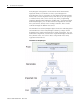
Chapter 1 Get Started with FuzzyDesigner Introduction Understanding FuzzyDesigner Topic Page Understanding FuzzyDesigner 9 Fuzzy Logic and Fuzzy Control Essentials 12 Specifications and Features 18 FuzzyDesigner is a software package for designing a fuzzy system to be implemented as a Hierarchical Fuzzy System (HFS).
Get Started with FuzzyDesigner FuzzyDesigner is designed to work with Rockwell Automation's Logix5000 family of controllers. A fuzzy system designed in FuzzyDesigner can be exported to an L5X Add-On instruction (AOI) format. You can then import the fuzzy AOI into any of your projects as needed. Fuzzy AOIs can be used by any of the programming languages (Function Block Diagram, Ladder Logic, or Structured Text).
Get Started with FuzzyDesigner 11 A Fuzzy Add-On instruction does not typically compete against standard controls found in Proportional-Integral-Derivative Controllers (PID). Fuzzy logic is a complementary tool, and fills functional gaps not addressed in standard controllers such as PIDs or Model Predictive Controllers. A development cycle of fuzzy logic solutions for Logix applications consists of multiple steps. 1. Design the fuzzy system in FuzzyDesigner. 2. Generate the fuzzy Add-On Instruction. 3.
Get Started with FuzzyDesigner Fuzzy Logic and Fuzzy Control Essentials This section introduces basic concepts used in a Fuzzy Add-On Instruction. The designer should know how to deal with an instruction’s inputs, outputs, and fuzzy If-Then rules that will be used to define input-output mapping. There are quite a number of systems or processes that are highly nonlinear, not well understood from the formal description point of view, or for which a mathematical model is not readily available.
Get Started with FuzzyDesigner 13 An expert may be an operator, a maintenance person, or a control engineer, who knows what adjustments are needed during process instability. These adjustments may include defining setpoints for process variables, defining control action in feedforward or feedback contro,l or setting gains of conventional controllers, and may be as simple as turning a valve or knob.
Get Started with FuzzyDesigner Crisp and Fuzzy For temperature readings, you can classify a reading into three sets, Low, Medium and High. Each set contains values in a given interval, and the intervals do not overlap. This means that a single reading or value is uniquely classified into one set. degree of membership (level of classification) Low Medium High Classification Result 1 1.00 Medium 0 0.0 High 0.
Get Started with FuzzyDesigner 15 Similar fuzzy terms are designed for the output variables, that is, Low, Medium, and High for compressor speed in our example. Fuzzy rules The way in which the classified inputs are treated when passing through rules is shown in the following figure for our compressor control example.
Get Started with FuzzyDesigner First, the numerical values of Temperature and Humidity get their meaning. In our case, the current setting of the Temperature is such that it is both 85% Medium and 40% High. Humidity is both 80% High and 50% Very High. The first rule is thus 80% true for the current inputs while the second rule is 40% true when using minimum for the and operation. The first rule states that, if 100% satisfied, the compressor should run at Medium speed.
Get Started with FuzzyDesigner 17 Nonlinear, Fuzzy Rule Based Supervisor of a PID Controller Plant States feedforward FUZZY FUZZY SUPERVISOR SUPERVISOR PID gains SP CV PID PID CONTROLLER CONTROLLER PLANT PLANT PV The great advantage of fuzzy supervision is that it can be applied to existing control and there is little danger of making errors in design.
Get Started with FuzzyDesigner Feedback Control System with Direct Fuzzy Controller Control system status Primary controls Setpoints FUZZY CONTROLLER Input filter Control Variables PLANT PLANT Output filter Process Variables A fuzzy controller with the above structure typically handles multiple inputs and generates multiple outputs. This system is recommended for experienced designers since control variables are direct functions of rules.
Get Started with FuzzyDesigner Component Membership functions AND OR Aggregation Inference (Activation) 19 Defuzzification Type/method if applicable Intermediate Linguistic Variable Max s-norm Output T-S Variable Max s-norm PID Controller Fuzzy System Analysis Tools Tool Description 2D/3D mesh plots Visualization of input-output static mappings generated by the fuzzy system or its specified subsystem Interactive plot control Color, grid, texture, zoom, and viewpoint management Tracing fu
Get Started with FuzzyDesigner FuzzyDesigner Mesh Plot with Simulated Path Fuzzy System Monitoring Feature Description Numerical and graphical display Monitoring of all internal variables Archiving Recording specified internal or external variables History graph Plotting history graph for on-line or off-line monitoring Fuzzy System Monitoring Through Numerical Displays Publication LOGIX-UM004A-EN-P - March 2007
Get Started with FuzzyDesigner 21 Fuzzy System Monitoring Through Plotting Historical Recordings and On-Line Update FuzzyDesigner Project Formats File Format Description XML .FSP – complete project file generated by FuzzyDesigner, .
Get Started with FuzzyDesigner Direct Support of Logix5000 controllers FuzzyDesigner, version 16.00 and later, supports Rockwell Automation's Logix5000 family of controllers. The fuzzy system designed using FuzzyDesigner can be exported to an RSLogix 5000 Add-On Instruction (AOI) XML import file. You can then import the fuzzy system into any of your projects as needed. Fuzzy AOI can be used by any of the programming languages (Function Block Diagram, Ladder Logic, or Structured Text).
Get Started with FuzzyDesigner 23 FuzzyDesigner Environment in Brief Publication LOGIX-UM004A-EN-P - March 2007
Get Started with FuzzyDesigner Project Tree view FuzzyDesigner Environment - Component examples Rule Block Input Linguistics Variable Input Port Publication LOGIX-UM004A-EN-P - March 2007 Output Liguistics Variable
Get Started with FuzzyDesigner 25 FuzzyDesigner Membership Functions Term Editor Degree of Fulfillment window FuzzyDesigner Rule Base - Rule Editor Publication LOGIX-UM004A-EN-P - March 2007
Get Started with FuzzyDesigner FuzzyDesigner Rule Interfacing FuzzyDesigner Defuzzification Methods DOF(negative) is maximal DOF(negative) DOF(zero) y* y* (MCA) (CA) Publication LOGIX-UM004A-EN-P - March 2007 y* y* y* (SOM) (MOM) (LOM)
Get Started with FuzzyDesigner 27 FuzzyDesigner PID Controller Publication LOGIX-UM004A-EN-P - March 2007
Get Started with FuzzyDesigner Notes: Publication LOGIX-UM004A-EN-P - March 2007
Chapter 2 FuzzyDesigner Component Library Introduction Component Interface The FuzzyDesigner Component Library offers eight components from which you can efficiently build distributed fuzzy systems.
FuzzyDesigner Component Library Library of Components The FuzzyDesigner Component Library offers the following components from which you can assemble fuzzy systems ranging from single input – single output systems to multiple input – multiple output systems with complex hierarchical structure of rules.
FuzzyDesigner Component Library 31 Trapezoidal Membership Function with Parameters (vertices): (a,b,c,d) 0 if x < a ⎧ ⎪ ( x − a) /(b − a) if x ∈ [a, b) ⎪⎪ A( x) = ⎨ 1 if x ∈ [b, c] ⎪( x − d ) /(c − d ) if x ∈ (c, d ] ⎪ 0 if x > d ⎪⎩ A(x) 1 0 a b c x d If a = b then A(a) = 1. If c = d then A(c) = 1. Trapezoidal membership functions can be used in input and output linguistic variable components.
FuzzyDesigner Component Library Inverse S-shaped Membership Function (cubic spline) with Parameters: (a,b,c,d) A(x) 1 if x≤a ⎧ ⎪ 2 3 a b − ⎛ ⎞ 1 ⎪ ( x − b) 2 ⎜ x − ⎟ if x ∈ (a, b] ⎪ (b − a )3 2 ⎠ ⎝ ⎪ A( x) = ⎨ 0 if x ∈ (b, c) ⎪ 2 3 d c − ⎛ ⎞ ⎪ ( x − c) 2 ⎜ x − ⎟ if x ∈ [c, d ) 2 ⎠ ⎪ (c − d ) 3 ⎝ 0 ⎪ 1 if x≥d ⎩ a b c d x If a = b then A(a) = 1. If c = d then A(c) = 1. Inverse S-shaped membership functions can be used in an input linguistic variable component.
FuzzyDesigner Component Library 33 User Defined Filter You set the numerator and denominator coefficients b0, b1, …bm and a1, …an directly (the parameters are entered in the specified order separated by the space character). Butterworth Low Pass Filter This filter can be created by specifying a normalized cutoff frequency q, taken from the interval [0.01, 1], and the order of the filter (1,2,3).
FuzzyDesigner Component Library Parameters • Name of the component • Vector b = [b0, b1,,bm] , coefficients of the filter transfer function numerator b(d)– optional • vector a = [a1, …,an], coefficients of the filter transfer function denominator a(d) – optional Input Linguistic Variable The fuzzy system Input Linguistic Variable component stores membership functions (fuzzy sets) of terms and is used for fuzzification (classification) of the component input – a crisp value.
FuzzyDesigner Component Library 35 This value is simply membership degree of value x* to fuzzy set A and can be interpreted as a degree to which the proposition (x* IS A) is true. An example of fuzzification of the crisp input value x* is shown in the figure Process of Crisp Input Fuzzification. The component input value is -0.3191. The component consists of three linguistic terms – negative, zero, and positive. The output of the component is the vector [0.6383, 0.3617, 0] – where 0.
FuzzyDesigner Component Library Connections The input link of the input linguistic variable is connectable to any of these components providing a crisp value: • • • • input Port component. output Linguistic Variable component. output Takagi-Sugeno Variable component. PID component. The output logical link of the input linguistic variable is connectable to components expecting a DOF value (as a result of fuzzification or defuzzification), such as the Rule Block component.
FuzzyDesigner Component Library 37 The Output Linguistic Variable component stores linguistic terms. Each linguistic term is defined by its fuzzy set, that is, the membership function and the name. The following membership functions are supported: • Trapezoidal membership function • Singleton membership function Linguistic terms are defined on the specified range [ymin, ymax] (universe of discourse).
FuzzyDesigner Component Library Centroid Average – CA generally An output value computed by this method is equal to the weighted average of the positions of the centroids of the output membership functions Aj weighted by their actual activation levels. The output value is computed as follows.
FuzzyDesigner Component Library 39 Defuzzification CA and MCA for trapezoids. Trapezoids are automatically transformed to singletons. CA = centroid method MCA = mean of maxima (to allow reaching limit values of the range) MCA CA CA MCA The output value is then computed in the same way as for singletons. Mean of Maxima – MOM generally This method computes the mean value of the interval at which the output fuzzy set reached the largest membership degree. It is defined as follows.
FuzzyDesigner Component Library Largest of Maxima – LOM generally The only difference to the previous method is that the maximum value of the interval is chosen. The defuzzified output is defined as follows. { } y* = largest ci Ai (ci ) = max ( Aj (c j ) ) j A(y) … … y* y Mean of Maxima, Smallest of Maxima, and Largest of Maxima methods are not continuous and are mainly used in applications on decision-making and classification when the task is to choose from several alternatives.
FuzzyDesigner Component Library 41 Output = term with maximal DOF = zero Output = Default Value, if all DOFs = 0 DOF(zero) is maximal Defuzzification SOM, MOM, LOM for trapezoids Trapezoids are automatically transformed to singletons. SOM MOM LOM The output value is then computed in the same way as for singletons.
FuzzyDesigner Component Library Connections The input link of the output linguistic variable can be connected to a component providing the DOF value (as a result of fuzzy inference), that is, the Rule Block component. The output value link of the output linguistic variable can be connected to components expecting a crisp value, such as: • Output Port component. • Input Linguistic Variable component. • Output Takagi-Sugeno Variable component (only crisp values are considered).
FuzzyDesigner Component Library 43 The consequent functions fi are typically chosen as instances of a suitable parameterized function, whose structure remains equal in all the rules and only the parameters vary. Most often, these functions are linear combinations of antecedent variables. In control engineering, each rule usually represents local dynamics in different state space regions and the consequent is given in the form of a state-space or an ARX model.
FuzzyDesigner Component Library The output Takagi-Sugeno Variable component consists of functional terms. Each functional term is defined by its parameters (a0, a1, … an) and its name (the parameters are entered in the specified order separated by the space character). The type of every linguistic term can be different. There are two supported functions. • Linear function: f(x1,x2,...xn) = a0 + a1 x1 + a2 x2 +...+ an xn • Constant function: f(x1,x2,...xn) = a0 Where x1,x2,...
FuzzyDesigner Component Library EXAMPLE 45 Different linear-state feedback controllers are to be smoothly activated for different process states and setpoints – scheduling controller gains. There are three rules.
FuzzyDesigner Component Library The input value link of the output Takagi-Sugeno variable can be connected to components providing a crisp value, such as: • • • • Input Port component. Output Linguistic Variable component. PID component. Output Takagi-Sugeno Variable component. The output value link of the output Takagi-Sugeno variable can be connected to components expecting a crisp value, such as: • Output Port component. • Input Linguistic Variable component.
FuzzyDesigner Component Library 47 If the component input link is connected to a single rule block, the output degrees of fulfillment just copy inputs. If the component input is connected to several rule blocks, the output degrees of fulfillment of stored linguistic terms are computed as a maximum of the corresponding input degrees of fulfillment.
FuzzyDesigner Component Library Supported Format of Rules Multiple notations are used in the explanation of the supported format of rules. • X1, X2,…, Xn – premise variables • Y1, Y2,…, Ym.
FuzzyDesigner Component Library 49 FuzzyDesigner also supports this s-norm (fuzzy OR operator): maximum: Smax (x, y) = max (x, y) The evaluation of the Rule Block is completed in three steps. 1. DOFs of all rules are computed from DOFs of the rule premise by using the selected t-norm. 2. DOFs of all conseqent variables terms are computed for every rule. These DOFs are obtained from DOFs computed in step 1, multiplied by weights of consequent variables. 3.
FuzzyDesigner Component Library You can also formulate the rule base schematically: • (small, negative) → (medium [0.9] , positive [1.0]). • (large, negative) → (small [0.8] , ). •( , positive) → (small [1.0] , positive [1.0]). In the following example, some premise variable DOFs are supposed. • Temperature: DOFtemp(small) = 0.4 , DOFtemp(large) = 0.8 • Pressure: DOFpress(negative) = 0.1 , DOFpress(zero) = 0.9 , DOFpress(positive) = 0.5 EXAMPLE Step 1: DOFs of all rules are computed.
FuzzyDesigner Component Library 51 Set of Rules Example Evaluation Procedure 1. (small, negative) Æ (medium [0.9] , positive [1.0]) 0.4 0.1 * 0.09 min premise part: DOF = 0.1 current zero , positive 0.0 , 0.1 voltage small , medium , large 0.08 , 0.0 , 0.0 current zero , positive 0.0 , 0.0 voltage small , medium , large 0.5 , 0.0 , 0.0 current zero , positive 0.0 , 0.5 voltage small , medium , large 0.5 , 0.09 , 0.0 current zero , positive 0.0 , 0.5 * 0.1 2. (large, negative) Æ (small [0.
FuzzyDesigner Component Library Connections The input logical link of the Rule Block can be connected to a component providing a DOF value (as a result of fuzzification or defuzzification), such as the: • • • • Input Linguistic Variable component. Output Takagi-Sugeno Variable component. Output Linguistic Variable component. Intermediate Linguistic Variable component.
FuzzyDesigner Component Library 53 The component can be used as a conventional PID controller with supervised parameters defined by component input links. The component output link provides a crisp value representing the control variable. The component functionality is defined through the equation format with the option of using either independent gains or dependent gains.
FuzzyDesigner Component Library ΔOk = (1 − α ) Ok − Ok −1 + αΔOk −1 Ts α= where 1 T 16 s + 1 D . Finally the control variable CV is computed in the following way: CVk = P ⋅ ( Ek + Itermk + D ⋅ ΔOk ) + Bias CVk = P ⋅ Ek + Itermk + D ⋅ ΔOk + Bias in the case of dependent gains and independent gains respectively. The controller can be used in two different modes – Manual mode and Automatic mode (default mode).
FuzzyDesigner Component Library 55 Zero crossing dead band control stops changing control variable (ΔCV = 0) when the process variable crosses the setpoint. The control variable is not changed as long as the process variable remains within the dead band interval.
FuzzyDesigner Component Library Parameters • Name of the component • Controller Gain parameters (P, I, D), Bias – specified by links to components providing crisp values or by user defined constant values • Setpoint value SP – specified by links to components providing crisp values or by user defined constant values • Sampling period Ts • Output limiting of control variable – YES or NO • Output limits – [CVmin, CVmax] (if YES) • Equation format – dependent or independent gains • Derivative input format
Chapter 3 FuzzyDesigner Graphical User Interface Introduction The FuzzyDesigner graphical user interface (GUI) is illustrated by a simple academic Ball and Beam experiment provided as one of the sample projects when you install FuzzyDesigner. Topic Page Setting Options 57 FuzzyDesigner Control Basics 59 The objective is to stabilize the ball at the desired position on the beam.
FuzzyDesigner Graphical User Interface Tool Bar The Tool Bar (see FuzzyDesigner Tool Bar) submenu on the View menu enables access to the commands for customizing the FuzzyDesigner tool bar. A tool bar button can be set as visible or invisible by clicking the appropriate Tool Bar submenu commands. FuzzyDesigner Tool Bar Status Bar The Status Bar (see FuzzyDesigner Status Bar) menu command on the View menu enables you to set the status bar of FuzzyDesigner as visible or as invisible.
FuzzyDesigner Graphical User Interface 59 FuzzyDesigner Tree View FuzzyDesigner Control Basics The controls in FuzzyDesigner are very similar to other Microsoft Windows applications, and are easy to use. FuzzyDesigner’s functions can be accessed from the main menu or by clicking the tool bar button commands. By right-clicking the tree view item or in the FuzzyDesigner project window, a related pop-up menu appears. You can also control most of the functions using these pop-up menus.
FuzzyDesigner Graphical User Interface FuzzyDesigner has two main modes, Design mode and Monitoring mode. FuzzyDesigner defaults to the Design mode, where you can design the project, set or reset options and use all application tools without any restriction. Use the Monitoring mode when you need to change the project parameters only, and leave the project design unchanged. Options and tools that can enable project design changes are restricted in the Monitoring mode.
FuzzyDesigner Graphical User Interface 61 Project FuzzyDesigner Main Menu Project Structure • • • • • • • • • • • New – creates a new project Open … – opens an existing project Close – closes the active project Close All – closes all open projects Save – saves the active project Save As … – save the active project with a different name Project Information … – displays the properties for the current project Preview – shows the preview of the currently active project Print … – prints the active project Re
FuzzyDesigner Graphical User Interface • Go to Design mode …/Go to Monitoring mode – switches the project between the Design mode and Monitoring mode (see section FuzzyDesigner Control Basics) • New Port – New Input Port … – see section Input Port – New Output Port … – see section Output Port • New Variable – New Input Linguistic Variable … – see section Input Linguistic Variable – New Output Linguistic Variable … – see section Output Linguistic Variable – New Output Takagi-Sugeno Variable … – see sect
FuzzyDesigner Graphical User Interface 63 • Tool Bar – Hide All Buttons – hides all tool bar buttons of the application – Show All Buttons – shows all tool bar buttons of the application – Create New Project – shows or hides the Create New Project tool bar button of the application – Open Project – shows or hides the Open Project tool bar button of the application – Save Active Project – shows or hides the Save Active Project tool bar button of the application – Undo – shows or hides the Undo tool bar but
FuzzyDesigner Graphical User Interface • Status Bar – shows or hides the status bar of the application • Tree View – shows or hides the Tree View tab control page of the application Tools FuzzyDesigner Main Menu Tools Structure • Options – Show in Status Area – check this menu item to set the FuzzyDesigner to the server mode. The FuzzyDesigner icon shows in the status area and the application should be closed only through the icon context menu.
FuzzyDesigner Graphical User Interface 65 Window FuzzyDesigner Main Menu Window • Tile – tiles all open windows in the application workplace • Cascade – cascades all open windows in the application workplace • Arrange Icons – arranges icons in the application workplace • Minimize All – minimizes all windows in the application workplace • Maximize All – maximizes all windows in the application workplace • Restore All – restores all windows to their normal size in the application workplace Help FuzzyDesig
FuzzyDesigner Graphical User Interface Tool Bar Menu This section lists all menu buttons in the tool bar menu (see FuzzyDesigner Tool Bar) of the FuzzyDesigner main window.
Chapter 4 FuzzyDesigner Projects Introduction The basic working unit in the FuzzyDesigner is a project. This chapter describes the concept of a project. Topic Page Working with Projects 67 Designing a Fuzzy System 72 Fuzzy System Components 75 Term Editor 102 Term Properties Dialog 105 Rule Editor 108 Port Order Editor 113 Watch 113 History Graph 117 2D Graph 122 3D Graph 125 A project is a set of data containing information related to a particular fuzzy system.
FuzzyDesigner Projects • Print – prints the project window of the currently active project • Recent Projects – shows the four most recent projects • Exit – closes FuzzyDesigner All opened projects and their components are seen in the Tree View tab control page. When you right-click a tree view node, a context sensitive menu appears.
FuzzyDesigner Projects 69 • Delete All – deletes all applied components with the appropriate type from the project. Component Type Tree View Node Context Menu There are component nodes of the applied components under the appropriate component type node of each opened project.
FuzzyDesigner Projects 3. When you select a fsp-file type, a file in the XML format with all project information will open. When the selected file has no information about the project graphical representation or about FuzzyDesigner GUI, the project will be opened with a default graphical representation and FuzzyDesigner GUI information (without the project description, for example). 4. Click Open.
FuzzyDesigner Projects 71 OK button - Accept the entered properties for the project. Cancel button – Click the button if you do not want to apply the changes, but you want to close the dialog. Project Information Dialog Saving a Project To save changes made in the active project, use the Project\Save main menu command. To save newly created projects, or to save to another project, use the Project\Save As main menu command.
FuzzyDesigner Projects To close all open projects, use the Project\Close All main menu command. FuzzyDesigner may display a dialog, prompting you to save your project before closing it. To save the project’s changes, click Yes. To close the project without saving the project’s changes, click No. To return to the project without saving or closing the project, click Cancel.
FuzzyDesigner Projects 73 Fuzzy System Project Window The fuzzy system project window enables the designer to create block diagrams of a fuzzy system by inserting and linking graphical objects, library components, and text. The window size is user defined, and accommodates any structure of a fuzzy system. Avoid moving any object outside of this area. If you right-click the empty Design Sheet window, the Design Sheet context menu (see Fuzzy System Project Window Context Menu) appears.
FuzzyDesigner Projects Selecting a Block Click an existing block to select it. Other previously selected objects are automatically unselected. To select multiple graphical objects, draw a bounding box around them with your mouse, or hold the CTRL key while clicking them. To select all graphical objects (blocks and texts) use the Select All item from Fuzzy System Project Window Context Menu (see section Fuzzy System Project Window). You can also select a block through the Tree View.
FuzzyDesigner Projects 75 You can change the internal parameters that define the block function by clicking the Block Properties menu item or by double-clicking the object. You can also modify internal parameters by using the Tree View. Blocks Context Menu Working with Text Use text to make comments in a fuzzy model. To insert text, select the Text Properties command in the Design Window context menu. If you enter only spaces or don’t enter any text, the text object is not created.
FuzzyDesigner Projects • PID Controller Components of the same type used more than once in the same project must have a unique name. The Input Port and the Input Linguistic Variable can share the same name. The name of the Input Linguistic Variable, Output Linguistic Variable, Output Takagi-Sugeno Variable and PID Controller used in the same project cannot be shared by the other components. The Output Port can share names with the Output Linguistic Variable.
FuzzyDesigner Projects 77 – Port General group box – Enter general parameters of a new or existing IP. • Port Name – Specify the IP name. This name will be used as the input parameter name when the fuzzy algorithm is compiled to an Add-On Instruction. • Use Filter – The IP input value can be filtered by a user-defined filter. Click the Use Filter check box to set up the Input Port filter. • Butterworth Lowpass Filter – Click this radio button to set the Butterworth Lowpass Filter parameters.
FuzzyDesigner Projects • Description tab dialog – Specify the description of a new or existing IP. Input Port Properties Dialog– Description Tab Dialog – Port Description – Enter the description of the IP. This description will be used as the input parameter description when the fuzzy algorithm is compiled to an Add-On Instruction. • Reset Filter State button – Click this button to reset the internal state of the implemented filter. • OK button – Accept the entered properties for the project.
FuzzyDesigner Projects 79 Input Linguistic Variable Use the Edit\New Variable\New Input Linguistic Variable main menu command or the New Input Linguistic Variable tool bar button to add a new Input Linguistic Variable (ILV) to the currently active project. Use the New Input Linguistic Variable project window context menu command to add a variable. First, the Input Linguistic Variable properties dialog appears. Click OK to add the component to the appropriate project.
FuzzyDesigner Projects • Unit tab dialog – Specify the unit of a new or existing ILV. Input Linguistic Variable Properties Dialog – Unit Tab Dialog – Predefined – Click this radio button to select the variable unit from the list of predefined units. • Variable of – Select one of the predefined quantities, which has the same meaning as the ILV. • In – Select one of the predefined units as the requested unit of the ILV. – User Defined – Click this radio button to select a user-defined variable unit.
FuzzyDesigner Projects 81 – Rescale Membership Functions of the Applied Terms – Click this check box to rescale the membership functions of all terms of the ILV. IMPORTANT The minimum value must be always lower then the maximum value. When the dialog for a new ILV is opened the default range is preset to –1 for minimum and 1 for maximum. • Terms tab dialog – The ILV properties dialog defines the variable through the following terms.
FuzzyDesigner Projects • Description tab dialog – Specify the description of a new or existing ILV. Input Linguistic Variable Properties Dialog – Description Tab Dialog – Variable Description – Enter the description of the ILV. • Term Editor button – Click this button to open the Term Editor (see section Term Editor), where the predetermined variable terms can be changed (count, names). • OK button – Accept the entered properties for the project.
FuzzyDesigner Projects 83 • General tab dialog – Specify all parameters of a new or existing OP. Output Port Properties Dialog – General Tab Dialog – Port Name – Specify the OP name. This name will be used as the output parameter name when the fuzzy algorithm is compiled to an Add-On Instruction. – Input Link – Set up the OP input link. The link can realize the connection between the OP and the Input Port, Output Linguistic Variable, Output Takagi-Sugeno Variable or the PID Controller.
FuzzyDesigner Projects • Cancel button – Click this button to leave the OP properties dialog. Any changes made are not applied. You can also click Close, at the top right corner of the dialog. Output Linguistic Variable Use the Edit\New Variable\New Output Linguistic Variable main menu command or the New Output Linguistic Variable tool bar button to add a new Output Linguistic Variable (OLV) to the appropriate fuzzy system project.
FuzzyDesigner Projects 85 • Unit tab dialog – Specify the unit of a new or existing OLV. Output Linguistic Variable Properties Dialog – Unit Tab Dialog – Predefined – Click this radio button to select the unit of the variable from the list of predefined units • Variable of – Select one of the predefined quantities, which has the same meaning as the OLV. • In – Select one of the predefined units as the requested unit of the OLV.
FuzzyDesigner Projects • Range tab dialog – Specify the range of the variable and its default value. Output Linguistic Variable Properties Dialog – Range Tab Dialog – Minimum – Specify the lower limit of the variable. – Maximum – Specify the upper limit of the variable. – Default Value – Set up the default value of the variable. The default value must be within the specified range of the variable.
FuzzyDesigner Projects 87 • Terms tab dialog – When the OLV properties dialog is open for defining the variable, you can specify the variable terms in the same way as was explained for the Input Linguistic Variable. Output Linguistic Variable Properties Dialog – Terms Tab Dialog – Count – the number of terms. – Type – the type of terms. – Names– predefined names of terms.
FuzzyDesigner Projects – Variable Description – Enter the description of the OLV. • Term Editor button – Click this button to open the Term Editor (see section Term Editor), where the default variable terms can be changed, for example, count and names. • OK button – Accept the entered properties for the project. • Cancel button – Click this button to leave the OLV properties dialog. Any changes made are not applied. You can also click Close, at the top right corner of the dialog.
FuzzyDesigner Projects 89 • General tab dialog – Specify the main properties of a new or existing OTSV. Output Takagi-Sugeno Variable Properties Dialog – General Tab Dialog – Variable Name – Specify the variable name. – Applied Input Links –All pins and applied input links of the OTSV are shown here. The component pins can be connected to the Input Ports, Output Linguistic Variables, Rule Blocks and the PID Controllers. – Available Input Links – Select an available feasible input link for the variable.
FuzzyDesigner Projects • Unit tab dialog – Specify the unit of a new or existing OTSV. Output Takagi-Sugeno Variable Properties Dialog – Unit Tab Dialog – Predefined – Click this radio button to select a predefined unit of the variable. • Variable of – Select one of the predefined quantities that has the same meaning as the OTSV. • In – Select one of the predefined units as the requested unit of the OTSV. – User Defined – Click this radio button to insert a user-defined unit of the variable.
FuzzyDesigner Projects 91 • Range tab dialog – Specify the range of the variable including its default value. Output Takagi-Sugeno Variable Properties Dialog – Range Tab Dialog – Minimum – Specify the lower limit of the variable range. – Maximum – Specify the upper limit of the variable range. – Default Value – Specify the default value of the variable. The default value must be within the variable range.
FuzzyDesigner Projects • Description tab dialog – Specify the description of a new or existing OTSV. Output Takagi-Sugeno Variable Properties Dialog – Description Tab Dialog – Variable Description – Enter the description of the OTSV. • Term Editor button – Click this button to open the Term Editor (see section Term Editor), where you can chage the terms of the variable. • OK button – Accept the entered properties for the project. • Cancel button – Click this button to close the OTSV properties dialog.
FuzzyDesigner Projects 93 The Intermediate Linguistic Variable properties dialog appears and a default name is assigned to the component. Click OK to add the component to the appropriate project. All Intermediate Linguistic Variable names must be unique in the same project. • General tab dialog – Specify the name of the IMLV. Intermediate Linguistic Variable Properties Dialog – General Tab Dialog – Variable Name – Enter the name of the variable.
FuzzyDesigner Projects – Names – Change default names and specify names of terms for the newly created intermediate variable. When the IMLV properties dialog is open for the existing variable, the names of terms already applied are shown. IMPORTANT When the IMLV properties dialog is open for an existing variable, then the terms count and the term names are visible, but you cannot change them in the properties dialog. • Description tab dialog – Specify the description of a new or existing IMLV.
FuzzyDesigner Projects 95 The Rule Block properties dialog appears and a default name is assigned to the component. Click OK to add the component to the appropriate project. Rule Block names must be unique in the same project. • General tab dialog – Specify the main properties of a new or existing RB. Rule Block Properties Dialog – General Tab Dialog – Block Name – Enter the block name. – T-norm Type – Set up the t-norm type for the block.
FuzzyDesigner Projects • Links tab dialog – Set up the RB input and output logical links. Rule Block Properties Dialog – Links Tab Dialog – Applied Input Logical Links Tab Dialog –The list box shows all applied input logical links of the block. – Applied Output Logical Links Tab Dialog – The list box shows all applied output logical links of the block. – New Logical Link combo box – Select one of the available input or output logical links that can be used for the block.
FuzzyDesigner Projects 97 • Description tab dialog – Specify the description of a new or existing RB. Rule Block Properties Dialog – Description Tab Dialog – Block Description – Enter the description of the RB. • Rule Editor button – Click this button to open the Rule Editor (see section Rule Editor), where you can change the block rule base, for example, add or delete rules. • OK button – Accept the entered properties for the project.
FuzzyDesigner Projects • General tab control page – Specify the main properties of a new or existing PIDC. PID Controller Properties Dialog – General Tab Dialog – PID Controller Name – Specify the controller name. – Input Links group box – Set up all available input links or values. • Process Variable – Set up required process variable link. • Set Point Link – Click the check box and select the set point link.
FuzzyDesigner Projects 99 • I Gain Value – When the I Gain Link check box is not checked, enter the I gain constant value. • D Gain Link – Click the check box and select the D gain link. • D Gain Value – When the D Gain Link check box is not checked, enter the D gain constant value. • Bias Link – Click the check box and select the bias link. • Bias Value – When the Bias Link check box is not checked, enter the bias constant value. • Manual Control – Select the manual control link.
FuzzyDesigner Projects • Equation Format – Specify the equation format of the controller. • Derivative Input – Specify the derivative input of the controller. • Sampling Period – Specify the sampling period of the controller. The period must be greater then zero and is the same for all PIDs applied in the same project. • Parameter b – Select the value of the parameter b entering • • • • • • the P ∗ ( b ∗ SP − PV ) term of the PIDC equation. The value of the parameter ranges from 0 to 1.
FuzzyDesigner Projects 101 – Gain Forgetting Factor group box – Specify the gain forgetting factor of a new or existing PIDC. • Value – Enter the controller gain forgetting factor value of the controller. The factor default value is set to 1 for a new PIDC. • Gain Forgetting Factor track bar – Specify the gain forgetting factor setting from slow tracking (minimum) to exact tracking (maximum). • Description tab dialog – Specify the description of a new or existing PID controller.
FuzzyDesigner Projects • Cancel button – Click this button to close the PIDC properties dialog. Any changes made are not applied. You can also click Close, at the top right corner of the dialog. Term Editor Default terms are defined for a variable when you add it to the project. The exception is the Output Takagi-Sugeno Variable.
FuzzyDesigner Projects 103 – Term Properties – Show the Term Properties dialog (see section Term Properties Dialog) of the currently selected term. IMPORTANT To show the Term Properties dialog of an already selected term, double-click anywhere in the membership function editor. To change the parameters of the selected term membership function only, right-click the term parameter and, in a click-and-drag operation, move it to the new position. Repeat as needed.
FuzzyDesigner Projects – Help – Show information about the Term Editor. IMPORTANT When you want to specify input values of the Input Linguistic Variable, you can use the membership function editor slider. Position the mouse cursor above the slider, click the right mouse button and move the slider to the desired position, then release the right mouse button. The actual slider position of the Input Linguistic Variable is seen in the Input Value text box below the membership function editor.
FuzzyDesigner Projects 105 Output Term Editor for The Output Linguistic Variable Term Properties Dialog When you click the Add Term tool bar button of a variable Term Editor dialog, the Term Properties dialog (see Input Term Properties Dialog or Output Term Properties Dialog) appears. A default name is assigned to a new term. • General group box – Specify the main properties of the term. – Term Name – Enter the term name.
FuzzyDesigner Projects • OK button – Accept the entered properties for the project. • Cancel button – Click this button to leave the Term Properties dialog. Any changes made are not applied. You can also click Close, at the top right corner of the dialog. IMPORTANT Open this dialog by double-clicking the right mouse button on the selected term in the Term Editor membership function editor, or from the table of term DOFs, or the Term Properties tool bar button of each Term Editor.
FuzzyDesigner Projects 107 Output Term Properties Dialog Output Term Properties Dialog for the Output Takagi-Sugeno Variable Publication LOGIX-UM004A-EN-P - March 2007
FuzzyDesigner Projects Rule Editor Click Rule Editor in the Rule Block properties dialog to open the Rule Editor dialog (see Rule Block Rule Editor with a Rule Base). You can also open the Rule Editor by double-clicking a Rule Block. Rule Block Rule Editor with a Rule Base The Rule Editor shows the following columns: • Index – Shows the index of a rule of the selected Rule Block rule base. • Active – Shows rule activity.
FuzzyDesigner Projects 109 Operations with Rules You can add, create, or delete rules. Adding a Rule To add a rule, click the first available blank row and a new rule with the correct index will be created. Repeat this if you want to add more rules. Creating a Rule With the Rule Editor, you can make or modify the rule base of the selected Rule Block.
FuzzyDesigner Projects 2. When you want to apply a NOT operator to the whole OR expression, check Apply NOT for the expression. 3. Click OK. OR Expression Editor When you set up a term in the consequent variable cell, you can select the weight of the consequent variable. All visible changes are stored in the appropriate Rule Block of the project immediately. Deleting a Rule When you click the first column, the appropriate rule will be marked as selected and the rule background will turn blue.
FuzzyDesigner Projects 111 b. Use the Number of Rules numeric control to decrease the number of rules you want to generate. c. Click the Remove Just Applied Rules check box to remove all already applied rules of the selected Rule Block. d. Click OK to generate the requested rules or click Cancel or Close (the top right dialog corner) to return to the appropriate Rule Editor dialog without any changes. • Shift Selected Rule Up – Click this button to shift the selected rule one position up.
FuzzyDesigner Projects • Close button – Click this button to close the Rule Editor dialog.
FuzzyDesigner Projects Port Order Editor 113 Use the Tools\Set Port Order main menu command to open the Port Order Editor dialog (see Port Order Editor Dialog), where you can change the order of the Input and Output Ports of the active project. Port Order Editor Dialog • Input Ports table – Select one of the applied Input Ports. • Output Ports table – Select one of the applied Output Ports. • Shift Port Up button – Click this button to shift any port up by one position.
FuzzyDesigner Projects • History Graph – Click this button to show the history graph. When a dialog (see Watch History Graph Properties Dialog) with a check box lists appears, choose values for the history graph. To view the history graph (see History Graph), click the Show button at the bottom of the dialog. When the history is empty, the graph is shown immediately after you press the History Graph button.
FuzzyDesigner Projects 115 • Close button – Click this button to close the Watch dialog.
FuzzyDesigner Projects Watch History Graph Properties Dialog Watch Save History Data Dialog Monitored data is saved in the ASCII format. The structure of the file is shown in the following table where: • NH is the history depth. • Ts is the sampling period. • telapsed is the relative time elapsing from the monitoring start. • tactual is the absolute computer time.
FuzzyDesigner Projects Sample Time [ms] Time Input Name 1 Input Name 2 … Output Name 1 telapsed - (NH -1)Ts tactual - (NH -1)Ts u1(telapsed - (NH -1)Ts) u2(telapsed - (NH -1)Ts) y1(telapsed - (NH -1)Ts) 117 … M telapsed – 2 Ts tactual – 2 Ts telapsed - Ts tactual - Ts u1(telapsed - Ts) u2(telapsed - Ts) y1(telapsed - Ts) telapsed tactual u1(telapsed) u2(telapsed) y1(telapsed) EXAMPLE The monitored fuzzy system is the Ball.
FuzzyDesigner Projects If the graph is absolute then the displayed scaling of vertical axis is valid for all curves, otherwise, the scaling is valid only for the labelled base curve. Its parameters are written in the separate window located in the left bottom corner of the graph main window. In the relative mode all curves are scaled to share the vertical range with the base curve. The vertical range of each curve can be changed in the legend context menu.
FuzzyDesigner Projects 119 • Base Variable Property – This is located on the left bottom corner of the main graph window. You can hide it by using a graph toolbar button. The window displays the base curve information (the curve on top of the legend). Unit, name, color, and range are displayed. History Graph History Graph Control – Context Menu Two context menus are available for history graph control. The first menu, shown below, appears when you right-click the graph.
FuzzyDesigner Projects • Zoom out – Zooms out of the graph. The minimum size depends on maximum (on an absolute scale) value of all displayed curves. • Zoom To Fit Window – Changes the graph size to best fit the window. • Zoom To Fit Base Vertical Range – Changes the graph size to best fit the base vertical range in the window. • Properties – Opens the dialog with graph properties (see Watch History Graph Properties Dialog). The second context menu appears you right-click the legend window.
FuzzyDesigner Projects 121 History Graph Control – Tool Bar The tool bar (see History Graph Tool Bar) has these three categories of buttons: • Changing the nature of graph range (relative or absolute) • Zooming in and out of a graph • Working with graph main window. The buttons are explained below. History Graph Tool Bar • Relative/Absolute Graph – Switches the graph from relative to absolute and vice versa. • Zoom In – Zooms in on the graph.
FuzzyDesigner Projects History Graph Control – Mouse Dragging You can change the size of the displayed graph by using your mouse. You can choose to zoom bidirectionally, horizontally, or vertically. 2D Graph 2D and 3D graphs are useful tools for off-line validation of a fuzzy system. Assume that the project deals with crisp inputs and outputs, which is the case in most control applications. The inference realized by the designed fuzzy system generates static input-output mapping.
FuzzyDesigner Projects 123 – X Axis – Select the Input Port or a disconnected Input Linguistic Variable as the x-axis of the 2D graph. – From – Specify the lower limit of the x-axis range. – To – Specify the upper limit of the x-axis range. – Y Axis – Select the Output Port, the Output Linguistic Variable or the Output Takagi-Sugeno Variable as the y-axis of the 2D graph. – From – Displays the lower limit of the y-axis range. – To – Displays the upper limit of the y-axis range.
FuzzyDesigner Projects 2D Graph Control – Context Menu The context menu appears when you right-click the 2D graph and have the structure displayed in the 2D Graph Context Menu. The meaning of all menu items is explained as follows. 2D Graph Context Menu • Zoom In – Zoom in on the graph. • Zoom Out – Zoom out of the graph. • Zoom To Fit Window – Zoom in or out of the graph to best fit the window. • Graph Line – Change the thickness and color of the graph line.
FuzzyDesigner Projects 125 • Path – Change the visibility and color of the path (trace), see section 2D Graph. You can also delete the complete path. • Graph Properties – Open the 2D Graph Properties Dialog (see section 2D Graph). 2D Graph Control – Tool Bar The tool bar (see 2D Graph Tool Bar) has three buttons: Zoom In, Zoom Out, and Zoom To Fit Window. All of them have the same function as the menu items with the same name.
FuzzyDesigner Projects – X Axis – Link the selected Input Port or a disconnected Input Linguistic Variable to the x-axis of the 3D mesh plot. – From – Sets the lower limit of the x-axis range. – To – Sets the upper limit of the x-axis range. – Y Axis – Links the selected Input Port or a disconnected Input Linguistic Variable to the y-axis of the 3D graph. – From – Sets the lower limit of the y-axis range. – To – Sets the upper limit of the y-axis range.
FuzzyDesigner Projects 127 3D Graph The 3D graph can be controlled either from the context menu or tool bar buttons. You can rotate the graph by using the mouse.
FuzzyDesigner Projects 3D Graph Control – Context Menu Right-click to display the context menu. The menu structure (see 3D Graph Context Menu) is explained below. 3D Graph Context Menu • Zoom In – Zoom in on the graph. • Zoom Out – Zoom out of the graph. • Zoom To Fit Window – Zoom in or out of the graph to best fit the window. • Rotate Left – Rotate the 3D graph to the left. • Rotate Right – Rotate the 3D graph to the right. • Rotate Up – Rotate the 3D graph up.
FuzzyDesigner Projects 129 Graph Grid Changes the graph grid visibility and color. Click the Default Setting option to restore the default settings. Graph Texture Changes the graph texture. There are four options. • Single color texture – the graph has the texture defined as color 1. • Gradient texture – the graph gets texture from gradient color. The lowest parts of the graph are assigned the color defined as color 2 and the highest parts of the graph, color 1.
FuzzyDesigner Projects 3D Graph Control – Tool Bar The tool bar (see 3D Graph Tool Bar) has nine buttons: Rotate Left, Rotate Right, Rotate Up, Rotate Down, Rotate CCW, Rotate CW, Zoom In, Zoom Out and Zoom To Fit Window. All of them have the function identical to the menu items described previously. 3D Graph Tool Bar 3D Graph Control – Mouse Dragging Drag the mouse to modify the 3D graph orientation.
Chapter 5 Fuzzy System Simulation Introduction FuzzyDesigner enables manual simulation of inputs and tracking of outputs generated by the fuzzy system. This feature serves as a basis for off-line tuning of a fuzzy system design parameters. All internal variables are also monitored and displayed during the input simulation run. Use Tools\Simulation main menu command to start the monitoring. FuzzyDesigner switches to Monitoring mode and a Simulation Watch dialog appears.
Fuzzy System Simulation Close button – Stops off-line simulation, and closes the Simulation Watch dialog. Returns FuzzyDesigner to Design mode.
Chapter 6 RSLogix 5000 Add-On Instruction Introduction You can use Add-On Instructions (AOIs) to deploy your fuzzy logic algorithm created with FuzzyDesigner.
RSLogix 5000 Add-On Instruction Generating a Fuzzy Add-On Instruction You can export a fuzzy system to an Add-On Instruction XML import file (.L5X). To generate the Add-On Instruction (AOI) for the active fuzzy project, click Tools>Add-On Instruction > Instruction Generator. The following dialog appears.
RSLogix 5000 Add-On Instruction 135 In RSLogix 5000 software, the Add-On Instruction names are stored in the same namespace as all other built-in instructions and data types (system or user-defined). Therefore, the Add-On Instruction name must be unique. Otherwise, an error message will appear during the import of the fuzzy Add-On Instruction. When exporting the fuzzy Add-On Instruction, you can select the folder to which you want to save the L5X file.
RSLogix 5000 Add-On Instruction Importing Add-On Instructions to RSLogix 5000 Projects You can use fuzzy Add-On Instructions in an RSLogix 5000 project. 1. Open the RSLogix 5000 project to which you want to import a fuzzy system Add-On Instruction. 2. Right-click the Add-On Instructions folder in the Controller Organizer. 3. Choose Import Add-On Instruction. The following dialog appears. 4. Select the Add-On Instruction (*.L5X file) you want to import to the RSLogix 5000 project.
RSLogix 5000 Add-On Instruction 137 5. Create an instance tag of the fuzzy Add-On Instruction. The type of the tag has to match the imported Add-On Instruction. 6. Create the tags (if not yet created) in which you want to store inputs and outputs of the fuzzy AOI. The type of these tags has to be REAL. 7. Add the fuzzy Add-On Instruction to code.
RSLogix 5000 Add-On Instruction 8. Enter parameters (operands) for the AOI.
RSLogix 5000 Add-On Instruction 139 • An RSLinx Topic corresponding to the Logix controller is created (see section Configuring RSLinx OPC Server Topic). If an RSLogix 5000 project is saved, then a default RSLinx Topic is created with a default name that corresponds to the Controller Name. • The fuzzy project used to generate the fuzzy AOI is open in FuzzyDesigner. Follow these steps to establish online communication with a Logix controller. 1.
RSLogix 5000 Add-On Instruction – If RSLinx software is installed on a remote computer, select the RSLinx Remote OPC Server option and specify a Node, then click Next. If communication is not established, contact your network administrator to configure DCOM settings.
RSLogix 5000 Add-On Instruction 141 3. Select the Add-On Instruction instance Tag to monitor the OPC address space under a specific Topic (the first branch under the tree root RSLinx OPC Server) and click Connect. Topic AOI Tag IMPORTANT The AOI instance Tag can be accessed through a Topic tied to corresponding Logix controller. If an RSLogix 5000 project is saved, then a default RSLinx Topic is created with a default name that corresponds to the Controller Name.
RSLogix 5000 Add-On Instruction If the selected AOI instance tag does not have the same parameters as the fuzzy project in FuzzyDesigner and only the project structures are the same, the following dialog is shown. This can happen if you have changed some parameters off-line, for example, the membership function position. If communication is successfully established, the following window appears. 4. Start monitoring by clicking on the Run Monitoring icon.
RSLogix 5000 Add-On Instruction 143 • If you make some changes, for example, changing membership function position in the fuzzy project in FuzzyDesigner and you want to apply the changes in Logix, click the Apply Changes to Logix icon Connection Panel. 5. To stop monitoring click the Stop Monitoring on the On-line icon.
RSLogix 5000 Add-On Instruction Configuring RSLinx OPC Server Topic The OPC topic represents a specific path to a processor. If an RSLogix 5000 project is saved, then a default RSLinx topic is created with a default name that corresponds to the Controller Name. To make sure that the selected RSLinx topic corresponds to the correct controller or to reconfigure or create a new RSLinx topic do the following steps. 1.
RSLogix 5000 Add-On Instruction 145 5. To create a new OPC topic, click New and enter a Topic name. Set a correct path to the controller in the browser. 6. Click Apply and then click Done. Modifying Fuzzy System Parameters Online When you modify fuzzy system parameters online, parameters are overwritten directly in the selected controller, that is, in the selected fuzzy system Add-On instruction tag.
RSLogix 5000 Add-On Instruction Modifying the fuzzy system parameters modifies a specific instance of the fuzzy Add-On Instruction, not the definition of the fuzzy Add-On Instruction. If you want to change the definition, you should create a new version of the fuzzy Add-On Instruction and import it onto your RSLogix 5000 project. Importing an Add-On Instruction to FuzzyDesigner FuzzyDesigner enables you to import the fuzzy Add-On Instruction XML file (.L5X) back to FuzzyDesigner.
Chapter 7 XML Format of a Fuzzy Project FuzzyDesigner enables you to export and import the fuzzy project in the XML format. In this chapter, the basic structure of the XML document corresponding to the fuzzy project designed in FuzzyDesigner is shown. An XML document consists of two main parts: the prolog and the document element (the root element). Prolog