
Owner's manual

6-12
PROFIBUS Communications Module
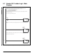
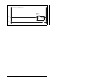
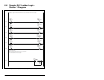
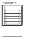
Figure 6.6 – Sample SLC Ladder Logic - Main Program (Continued)
Execute LAD 4 - Station 2 Drive Logic
0006
JSR
Jump To Subroutine
SBR File Number U:4
JSR
The PROFIBUS scanner is configured for 28 bytes (14 words) of outputs for each drive. Two drives require 48 bytes (28 words).
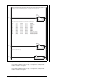
Station 1 Station 2 Description
M0:1.0 (N20:0) M0:1.14 (N20:14) Logic Command
M0:1.1 (N20:1) M0:1.15 (N20:15) Speed Reference
M0:1.2 (N20:2) M0:1.16 (N20:16) Datalink A1
M0:1.3 (N20:3) M0:1.17 (N20:17) Datalink A2
M0:1.4 (N20:4) M0:1.18 (N20:18) Datalink B1
M0:1.5 (N20:5) M0:1.19 (N20:19) Datalink B2
M0:1.6 (N20:6) M0:1.20 (N20:20) Datalink C1
M0:1.7 (N20:7) M0:1.21 (N20:21) Datalink C2
M0:1.8 (N20:8) M0:1.22 (N20:22) Datalink D1
M0:1.9 (N20:9) M0:1.23 (N20:23) Datalink D2
M0:1.10 (N20:10) M0:1.24 (N20:24) Parameter Protocol Word #1
M0:1.11 (N20:11) M0:1.25 (N20:25) Parameter Protocol Word #2
M0:1.12 (N20:12) M0:1.26 (N20:26) Parameter Protocol Word #3
M0:1.13 (N20:13) M0:1.27 (N20:27) Parameter Protocol Word #4
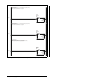
0007
COP
Copy File
Source #N20:0
Dest #N21:0
Length 28
COP
XMIT Data
Word 0
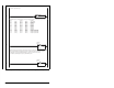
PROFIBUS scanners vary from manufacturer to manufacturer in how the bytes are ordered in a word. For example, some PROFIBUS
scanners operate with high & low bytes swapped (the value "1234" is represented as "3412"). The WRITE data is copied into
N21: and the bytes are reversed in the SWP instruction below so a value such as "3412" is viewed as "1234".
N21: contains the actual write data that is being sent to the PROFIBUS scanner.
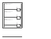
0008
SWP
Swap
Source #N21:0
Length 28
SWP
XMIT Data
Word 0