
Owner's manual


Using I/O Messaging
6-7
Parameter Settings
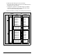
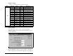
Scanner Settings
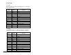
An SST-PFB-SLC scanner is in slot 1 of the SLC rack and
configured as Station 0. The Advanced I/O Configuration is set up
as shown in figure 6.3.
The two PROFIBUS modules are set up as Station 1 and Station 2,
and are configured as 14 words input & output each. See chapter 5.
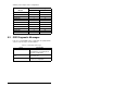
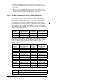
Table 6.1 – Parameter Settings for Sample SLC Program
Device Parameter Name Value Description
SP600
90 Speed Ref A Sel 22 ‘DPI Port 5’ (RECOMM-PBUS)
300 Data In A1 140 Points to Accel Time 1 (140)
301 Data In A2 142 Points to Decel Time 1 (142)
302 Data In B1 100 Points to Jog Speed (100)
303 Data In B2 155 Points to Stop Mode A (155)
304 Data In C1 101 Points to Preset Speed 1 (101)
305 Data In C2 102 Points to Preset Speed 2 (102)
306 Data In D1 103 Points to Preset Speed 3 (103)
307 Data In D2 104 Points to Preset Speed 4 (104)
310 Data Out A1 140 Points to Accel Time 1 (140)
311 Data Out A2 142 Points to Decel Time 1 (142)
312 Data Out B1 100 Points to Jog Speed (100)
313 Data Out B2 155 Points to Stop Mode A (155)
314 Data Out C1 101 Points to Preset Speed 1 (101)
315 Data Out C2 102 Points to Preset Speed 2 (102)
316 Data Out D1 103 Points to Preset Speed 3 (103)
317 Data Out D2 104 Points to Preset Speed 4 (104)
RECOMM-PBUS 11 DPI I/O Config xxx1 1111 Enables Cmd/Ref, Datalinks A-D
Figure 6.3 – Advanced I/O Configuration