
Owner's manual


3-6
PROFIBUS Communications Module
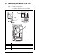
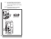
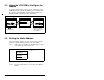
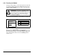
Step 4. For 1-20 HP SP600 drives, fold the Internal Interface
cable behind the module and mount the module on the
drive using the four captive screws. See figure 3.6.
For frame 2 and larger SP600 drives, mount the module
on the drive using the four captive screws to secure and
ground it to the drive.
Important: All screws must be tightened since the module is
grounded through a screw. The recommended
tightening torque is 0.9 N-m (8 in-lb).
Figure 3.6 – Mounting and Grounding the PROFIBUS Module
Module
Drive
Internal Interface cable
folded behind the module
and in front of the drive.
SP600 Drive
SP600 Drive
Frame 2 and Lar
g
er
1-20 HP