
Owner's manual

Getting Started
2-1
CHAPTER 2
Getting Started
This chapter provides:
• A description of the PROFIBUS module components
• A list of parts shipped with the module
• A list of user-supplied parts required for installing the module
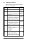
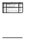
• An installation checklist
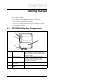
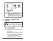
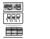
2.1 PROFIBUS Module Components
Status Indicators Three LEDs to indicate the status of the
connected drive, module, and network.
Refer to chapter 8 for more information
about the LEDs.
DPI Connector A 20-pin, single-row shrouded male
header. An Internal Interface cable
connects to this connector and a
connector on the drive.
PROFIBUS
Connector
A 9-pin, female D-Sub connector.
Node Address
Switches
Switches to set the node address.
Figure 2.1 – Components of the PROFIBUS Module