
User guide

7-14
Interbus Communications Module
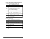
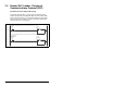
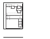
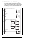
In the sample ladder logic program, the user would load these
registers before calling the subroutine to perform the PCP Write:
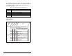
Figure 7.8 – Writing Flt Cfg A1 (12) to an RECOMM-IBUS Interbus Module
1 = RECOMM-IBUS
Message
CR# = 2 (Station 1.0)
N23:0
Request
2
2
SLC Address
Description
Value (Hex)
N23:1
1
1= 20-COMM-I
1
Value (Dec)
N23:2
6
6
Parameter # = 6
N23:3
N23:4
N23:5
1
2
0
1
2
0
1 byte data write
Data Word 1 = 2 (Zero Data)
Data Word 2 not used
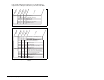
1 = RECOMM-IBUS
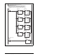
Message
Command word = 8 = PCP Write (bit 3 ON)
N23:10
Command
8
8
SLC Address
Description
Value (Hex)
N23:20
N23:13
N23:12
N23:11
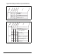
N23:21
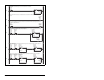
Reply
2
2048
0
8
-32,760
CR# = 2 (Station 1.0)
Sub Index not used
Number of words following = 2
CR# = 2 (Station 1.0)
2FC1
2
800
8
8008
N23:16
0
Value (Dec)
Result = 0 (success)
N23:23
0
2
2
0
2
2
N23:22
N23:24
"8000" (bit 15 ON) indicates Reply message present
Status word:
"0008" (bit 3 ON) echo's the command (PCP Write)
2FB6h is the start of the 20-COMM-I parameters (Pr.1)
Index = 2FB5h+Ch = Parameter 12 [Flt Cfg A1 In]
C hex = 12 dec = Parameter 12 [Flt Cfg A1 In]
Echo of the Command Word (PCP Write)
N23:14
N23:15
4
00
4
00000800 hex = 2048 decimal
4 bytes of data following
12225
Index = 2FB5h + Ch = Flt Cfg A1 In (12)
2FB6h is the start of RECOMM-IBUS parameters
C hex = 12 dec = Flt Cfg A1 In (12)