
User guide

Configuring the Interbus Scanner
5-3
PIDD and PODD parameters are used to identify what will be
transmitted on the network and the amount of network I/O the CMD
software will allocate on the scanner.
5.3 Configuring the Network Using CMD
Software
Before starting the network configuration process, make sure the
PC running CMD software is connected to the SST scanner (a null
modem cable is supplied with the scanner). The SLC and drives
need to be connected to the Interbus network and powered in order
for CMD software to configure the network. The CMD software tool
automatically creates a Reliance Electric sub-folder (in the Slaves
folder), if it does not already exist.
CMD needs to be in Extended Mode to configure the network. A
password (supplied by Phoenix Contact along with the CMD
software), is requested for this functionality each time CMD is
started. After CMD has started, you can also click O
ptions/
E
xtended (Function Scope) to enter the password.
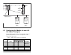
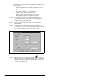
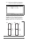
Step 1. Select F
ile / New from the pull-down menu to create a
new project. (See figure 5.2.)
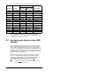
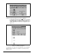
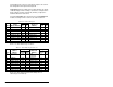
28 PIDD W4 Cfg 12198 2FA6 Datalink B1 Out
30 PIDD W5 Cfg 12199 2FA7 Datalink B2 Out
32 PIDD W6 Cfg 12200 2FA8 Datalink C1 Out
34 PIDD W7 Cfg 12201 2FA9 Datalink C2 Out
36 PIDD W8 Cfg 12202 2FAA Datalink D1 Out
38 PODD W0 Cfg 12184 2F98 Logic Command
40 PODD W1 Cfg 12185 2F99 Reference
42 PODD W2 Cfg 12188 2F9C Datalink A1 In
44 PODD W3 Cfg 12189 2F9D Datalink A2 In
46 PODD W4 Cfg 12190 2F9E Datalink B1 In
48 PODD W5 Cfg 12191 2F9F Datalink B2 In
50 PODD W6 Cfg 12192 2FA0 Datalink C1 In
52 PODD W7 Cfg 12193 2FA1 Datalink C2 In
54 PODD W8 Cfg 12194 2FA2 Datalink D1 In
Table 5.1 – Module Parameter Settings for Ladder Example (Continued)
Parameter Name
Value
Description
Binary/
Decimal Hexadecimal