
User guide

5-2
Interbus Communications Module
5.2 Configuring the Module for use with
the Ladder Examples
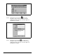
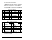
Prior to setting up the SST Interbus scanner with CMD software, the
parameters listed in table 5.1 need to be configured to use the
sample ladder logic program.
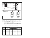
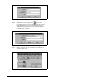
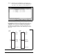
Figure 5.1 – Sample Interbus Network
Fault LED
COMM LED
Interbus
RS232 Port
REMOTE OUT
Config
SP600 Drive
Station 1.0
(CR=2)
SP600 Drive
Station 2.0
(CR=3)
Interbus Scanner in
Multi-Module Controller
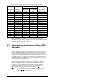
Table 5.1 – Module Parameter Settings for Ladder Example
Parameter Name
Value
Description
Binary/
Decimal Hexadecimal
8 DPI I/O Config xxx1 1111 001F Enable Cmd/Ref,
Datalinks A-D
20 PIDD W0 Cfg 12186 2F9A Logic Status
22 PIDD W1 Cfg 12187 2F9B Feedback
24 PIDD W2 Cfg 12196 2FA4 Datalink A1 Out
26 PIDD W3 Cfg 12197 2FA5 Datalink A2 Out