
User guide


4-4
Interbus Communications Module
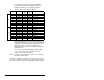
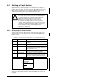
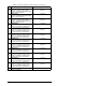
To configure the module for Logic Command/Status,
Reference/Feedback and the maximum number of
Datalinks enabled in see the example in table 4.3.
Note that Datalink D2 is not used in this example because
maximum configuration has been reached. The maximum
configuration is shown to illustrate utilizing all 9 words of
inputs and 9 words of outputs. Depending on your
application needs, any subset of the above example can
be implemented.
The corresponding DPI I/O Config (8) setting would be
“11111” for all of the above information to transfer
between the module and the drive.
Step 5. Reset the module. Refer to the section 4.4.3, Resetting
the Module, in this chapter.
The module is ready to receive I/O from the master (i.e., scanner).
You must now configure the scanner to recognize and transmit I/O
to the module. Refer to chapter 5, Configuring the Interbus Scanner.
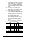
Table 4.3 – Module I/O Configuration Example
Parameter # Name Value
(Hex)
Value
(Dec)
Description
20 PIDD W0 Cfg 2F9A 12186 Logic Status (default)
22 PIDD W1 Cfg 2F9B 12187 Feedback (default)
24 PIDD W2 Cfg 2FA4 12196 Datalink A1 Out
26 PIDD W3 Cfg 2FA5 12197 Datalink A2 Out
Input 28 PIDD W4 Cfg 2FA6 12198 Datalink B1 Out
30 PIDD W5 Cfg 2FA7 12199 Datalink B2 Out
32 PIDD W6 Cfg 2FA8 12200 Datalink C1 Out
34 PIDD W7 Cfg 2FA9 12201 Datalink C2 Out
36 PIDD W8 Cfg 2FAA 12202 Datalink D1 Out
38 PODD W0 Cfg 2F98 12184 Logic Command (default)
40 PODD W1 Cfg 2F99 12185 Reference (default)
42 PODD W2 Cfg 2F9C 12188 Datalink A1 In
44 PODD W3 Cfg 2F9D 12189 Datalink A2 In
Output 46 PODD W4 Cfg 2F9E 12190 Datalink B1 In
48 PODD W5 Cfg 2F9F 12191 Datalink B2 In
50 PODD W6 Cfg 2FA0 12192 Datalink C1 In
52 PODD W7 Cfg 2FA1 12193 Datalink C2 In
54 PODD W8 Cfg 2FA2 12194 Datalink D1 In