
User guide


Installing the Interbus Module
3-3
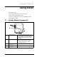
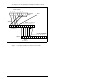
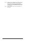
See figure 3.1 for an explanation of wiring an Interbus network.
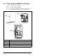
Step 5. Connect the Interbus connector to the module.
Figure 3.1 – Sample Network Wiring
DO DI COM /DO /DI
/DO1 DO1 /DI1 DI1 GND PE
/DO2 DO2 /DI2 DI2 GND RBST PE
/DO2 DO2 /DI2 DI2 GND RBST PE
/DO1 DO1 /DI1 DI1 GND PE
1 2 3 4 5 6 7 8 9
1 2 3 4 5 6
1 2 3 4 5 6 7
1 2 3 4 5 6 1 2 3 4 5 6 7
jumper
Shield
9-pin D-shell
Station 1
jumper
SST SLC Scanner
Station 2
Bus In
Bus Out
Bus Out
Bus In
(See Table 3.2)
(See Table 3.2)(See Table 3.2)
(See Table 3.1)
(See Table 3.1)