
User guide


Getting Started
2-1
C
HAPTER
2
Getting Started
This chapter provides:
•
A description of the Interbus module components
•
A list of parts shipped with the module
•
A list of user-supplied parts required for installing the module
•
An installation checklist
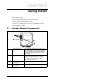
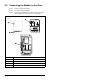
2.1 Interbus Module Components
Status Indicators Five LEDs that indicate the status of the
connected drive, module, and network.
Refer to chapter 8, Troubleshooting the
Interbus Module and Network, for more
information.
DPI Connector A 20-pin, single-row shrouded male
header. An Internal Interface cable is
connected to this connector and a
connector on the drive.
Bus In Interbus
Connector
One 6-pin plug-in connector.
Bus Out Interbus
Connector
One 7-pin plug-in connector.
Figure 2.1 – Components of the Interbus Module