
Owner manual

5-10
ControlNet Communications Module
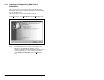
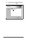
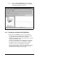
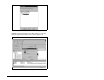
Step 3. When the network browse is complete, a graphical view of
the network is displayed. In this example (figure 5.13), the
ControlNet network consists of a PLC-5C/40C controller,
two SP600 drives, and a PC using a 1784-PCC.
The symbol indicates the device shown on the
network does not exist in the configuration file, but it was
found on the network. Double-click on the PLC-5C/40C
icon.
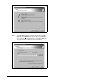
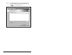
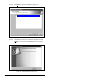
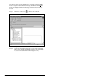
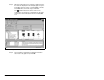
Step 4. The ControlNet configuration box displays information
about each node (figure 5.14). Click
OK.
Figure 5.13 – Sample ControlNet Configuration Screen
SP600 SP600