
Owner manual

Getting Started
2-1
C
HAPTER
2
Getting Started
This chapter provides:
•
A description of the ControlNet module components
•
A list of parts shipped with the module
•
A list of user-supplied parts required for installing the module
•
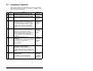
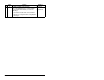
An installation checklist
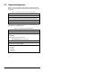
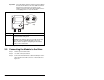
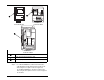
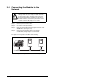
2.1 ControlNet Module Components
➊
Status Indicators Four LEDs that indicate the status of the
ControlNet channel(s), DPI, and the module. Refer
to chapter 8 for more information.
➋
DPI Connector A 20-pin, single-row shrouded male header. An
Internal Interface cable is connected to this
connector and a connector on the drive.
➌
Channel A BNC
Receptacle
Channel “A” BNC connection for the ControlNet
cable.
➍
Channel B BNC
Receptacle
Channel “B” BNC is an optional connection for the
redundnat ControlNet cable.
➎
ControlNet Node
Address Switches
Switches for setting the node address.
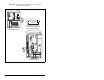
Figure 2.1 – Components of the ControlNet Module
➊
➋
➌➍
➎