
User guide


Getting Started
2-1
CHAPTER 2
Getting Started
This chapter provides:
• A description of the RS485 DF1 module’s components
• A list of parts shipped with the module
• A list of user-supplied parts required for installing the module
• An installation checklist
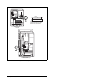
Status Indicators Four LEDs to indicate the status of the
connected drive, module, and network.
Refer to chapter 6 for more information
about the LEDs.
DPI Connector A 20-pin, single-row shrouded male
header. An Internal Interface cable
connects to this connector and one on
the drive.
RS485 DF1 Connector A 6-pin connector to which a 6-pin
linear plug can be connected.
Node Address Switches Switches to set the node address.
Data Rate Switch Switch to set the RS485 DF1 data rate
at which the module communicates.
Figure 2.1 – Components of the RS485 DF1 Module